
Dedusting system special for scrap steel crushing

A dust removal system and steel scrap technology, applied in the field of machinery, can solve the problems of dust removal system explosion, reduce maintenance times, and reduce intangible costs

Pending Publication Date: 2022-03-18
唐山惠玛自动化工程技术有限公司
View PDF0 Cites 0 Cited by
  • Summary
  • Abstract
  • Description
  • Claims
  • Application Information

AI Technical Summary

Problems solved by technology

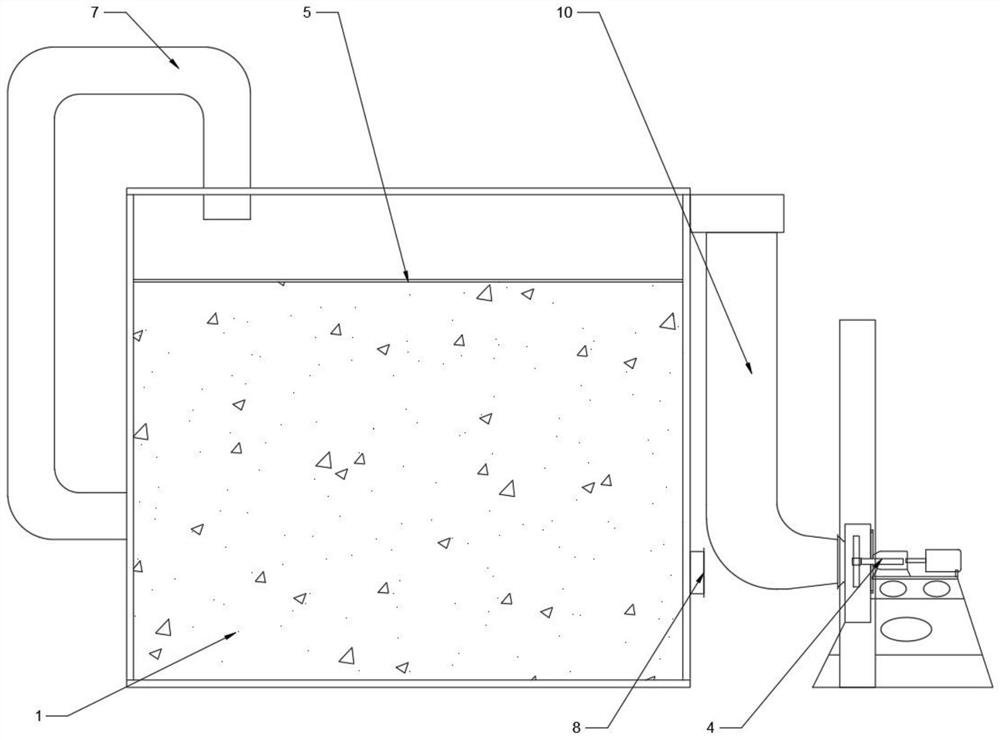
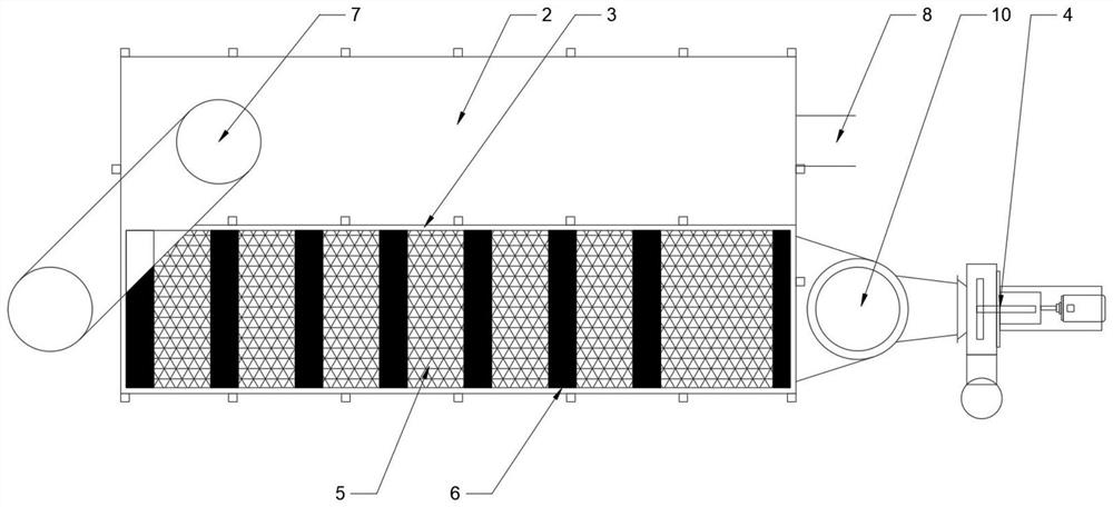
[0009] Compared with the prior art, the present invention has the advantages of solving the problems of explosion, fire, large dust, pipeline blockage, ash unloading jam, and dirty finished products in the dust removal system, and the long-term use of the pipeline without blockage, eliminating the need for manual dredging of the pipeline; the production line There will be no fugitive dust, which will purify the working environment and improve production efficiency; the unique design structure will not generate secondary dust and purify the working environment; the unique internal structure design will not catch fire and dust explosion; the unique appearance structure guarantees The airtightness of the dust removal system is improved, the air volume will not be lost, and the produced materials are also guaranteed to be clean; the simple structure design of the single body type, the spraying and dust cleaning are all done automatically, and the simple and simple structure can extend the daily maintenance cycle. , and reduce the number of maintenance, thereby reducing the intangible cost; in the production process, even if the crusher produces flames for a long time, the dust removal system can also guarantee normal operation and meet the environmental protection standards

Method used


Image

  • Dedusting system special for scrap steel crushing
  • Dedusting system special for scrap steel crushing
  • Dedusting system special for scrap steel crushing

Examples


Embodiment Construction

[0018] The present invention will be described in further detail below in conjunction with the accompanying drawings.

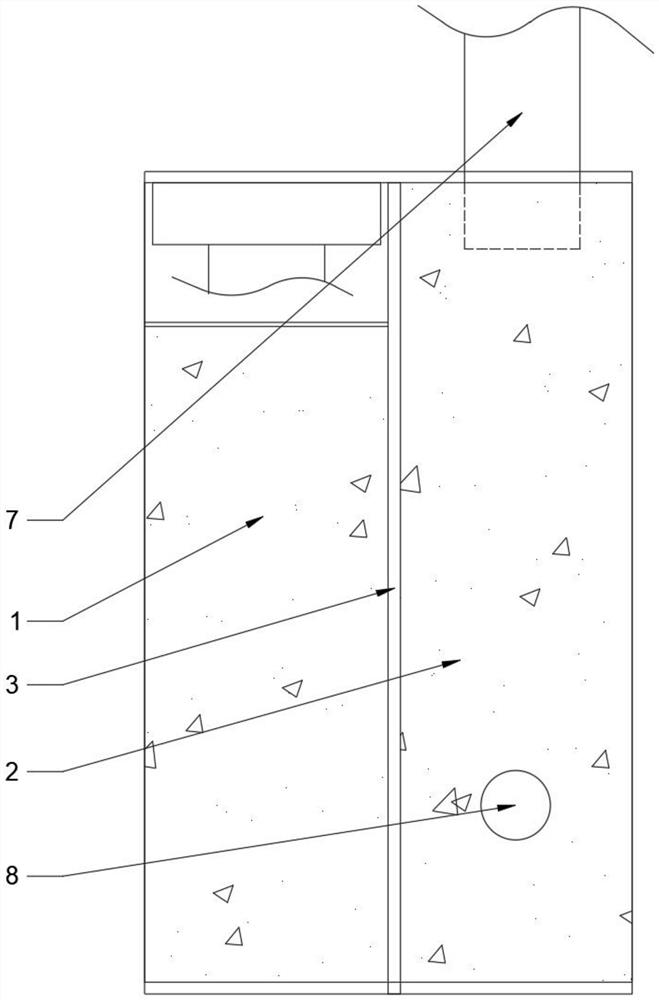
[0019] When the present invention is implemented in practice, a special dust removal system for scrap steel crushing includes a dust removal cabin 1 and a separation cabin 2, a partition wall 3 is provided between the dust removal cabin 1 and the separation cabin 2, and a dust removal fan is connected to one side of the dust removal cabin 1 4. There are dust filter cloths 5 inside the dust removal cabin 1, and the dust filter cloths 5 are arranged at equidistant intervals. There is a corridor 6 at the interval between the dust filter cloths 5. The dust removal cabin 1 and the separation cabin 2 are connected by a pipe 7. One side of the separation cabin 2 An air inlet 8 is provided, and an ash shoveling door 9 is provided at the bottom of the dust removal cabin 1 and the separation cabin 2 .

[0020] As an improvement, the dust filter cloth 5 is arranged near...


PUM


Abstract

The special dust removal system comprises a dust removal cabin and a separation cabin, a separation wall is arranged between the dust removal cabin and the separation cabin, one side of the dust removal cabin is connected with a dust removal fan, dust raising filter cloth is arranged in the dust removal cabin and arranged at equal intervals, and a corridor is arranged at the interval of the dust raising filter cloth; the dust removal cabin is connected with the separation cabin through a pipeline, an air inlet is formed in one side of the separation cabin, and dust shoveling gates are arranged at the bottoms of the dust removal cabin and the separation cabin. Compared with the prior art, the dust removal system has the advantages that the problems of explosion, fire catching, heavy raised dust, pipeline blockage, dust discharging blockage, dirty finished products and the like of the dust removal system are solved.

Description

technical field [0001] The invention relates to the field of machinery, in particular to a special dust removal system for scrap steel crushing. Background technique [0002] There are many similar problems in environmental protection treatment during the production of scrap steel crushers on the market as follows: [0003] Problem 1. Since the car shell contains many flammable items such as sponge, rubber, cotton wool, oil, etc., it is easy to cause explosion and fire when it is broken. [0004] Problem 2: Due to the large amount of raw material waste, the finished product is extremely dirty, and it is difficult to clean it if the dust removal equipment is unreasonable. [0005] Problem 3: The design of the general dust removal system is unreasonable, resulting in the blockage of the air duct, the jamming of the ash discharge valve and the burning of the motor, the cleaning of the filter bag is not clean, and the unreasonable internal structure of the dust collector is eas...

Claims


Application Information

Patent Timeline
IPC IPC(8): B01D50/40B01D50/00B01D45/02B01D45/16B01D47/06B01D49/00
CPCB01D47/06B01D45/02B01D45/16B01D50/00B01D49/00Y02A50/2351
Inventor 单智民
Owner 唐山惠玛自动化工程技术有限公司
Learn More