
Circulating electroplating equipment for machining and use method of circulating electroplating equipment

A kind of electroplating equipment and machining technology, applied in the direction of plating tank, electrolysis process, electrolysis components, etc., can solve the problems of increasing the cost of electroplating and large power consumption.

Inactive Publication Date: 2022-03-15
肖灯彪
View PDF1 Cites 3 Cited by
  • Summary
  • Abstract
  • Description
  • Claims
  • Application Information

AI Technical Summary

Problems solved by technology

[0005] The purpose of the present invention is to solve the disadvantages existing in the prior art that multiple servo motors need to be used in the process of electroplating, so that the consumption of electric energy is relatively large and the cost of electroplating is increased. Circulation electroplating equipment for machining and method of use thereof

Method used


Image

  • Circulating electroplating equipment for machining and use method of circulating electroplating equipment
  • Circulating electroplating equipment for machining and use method of circulating electroplating equipment
  • Circulating electroplating equipment for machining and use method of circulating electroplating equipment

Examples


Embodiment 1

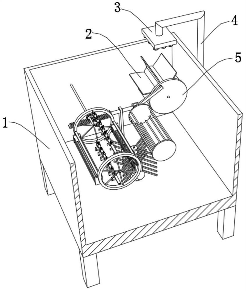
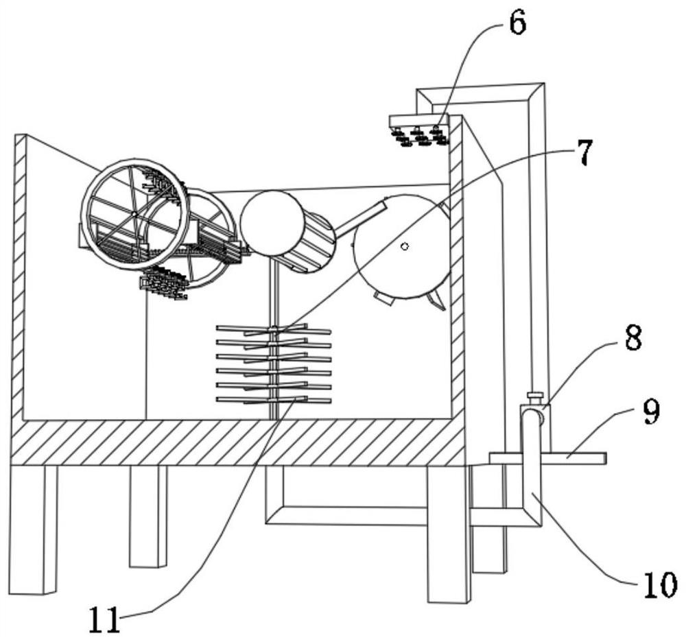
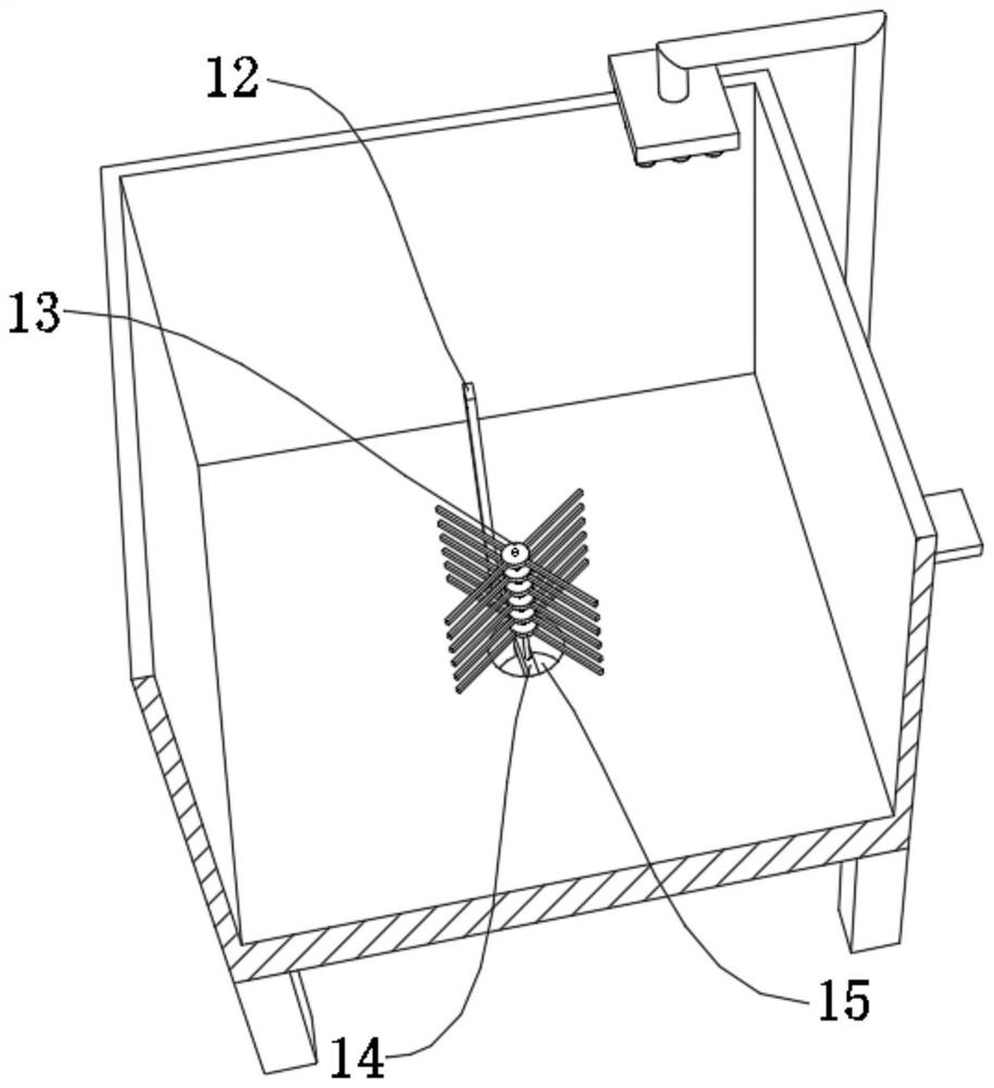
[0039] A kind of cycle electroplating equipment for mechanical processing, such as Figure 1-4As shown, it includes an electroplating box 1 and a return mechanism. The inner wall of one side of the electroplating box 1 is rotatably connected with a guide column 20, and the outer wall of the guide column 20 is fixed with more than two arc-shaped toggle plates 2 by bolts. The outer wall of one side of the guide column 20 is fixed with a rotating disk 5 by bolts, the outer wall of one side of the rotating disk 5 is rotatably connected with a rocker 21, and the outer wall of the rocker 21 is rotatably connected with a bracket 19, and the outer wall of one side of the bracket 19 is rotatably connected with a bracket 19. The sliding column 22 is fixed by bolts, the outer wall of one side of the sliding column 22 is fixed with a rack 17 by bolts, the inner wall of the bottom of the electroplating box 1 is fixed by bolts to limit the limit plate 12, and the outer wall of the sliding co...

Embodiment 2

[0044] A kind of cycle electroplating equipment for mechanical processing, such as Figure 1-3 , Figure 6 As shown, in order to electroplate the larger electroplated parts; this embodiment makes the following additions on the basis of embodiment 1: the outer wall of one side of the bracket 19 is fixed with a hollow cylinder 32 by bolts, and the inner wall of the circumference of the hollow cylinder 32 A rotating rod 33 is connected in rotation, and the outer wall of the circumference of the rotating rod 33 is welded with a universal ball 31, and the spherical outer wall of the universal ball 31 is welded with a connecting column 34, and the outer wall of one side of the connecting column 34 is fixed with a hollow frame 35 Larger electroplating parts can be placed by being provided with hollow frame 35, and hollow frame 35 can move synchronously with the horizontal movement of support 19 simultaneously, thereby can guarantee that electroplating solution can evenly act on the l...

Embodiment 3

[0048] A method for using the cycle electroplating equipment for mechanical processing described in embodiment 1, comprising the following steps:

[0049] S1: Place the electroplated parts according to the different types;

[0050] S2: Start the booster pump 8 to make the electroplating solution flow back;

[0051] S3: Use the sliding column 22 to drive the first mounting frame 16 and the second mounting frame 26 to rotate, so that the electroplating parts and the electroplating solution are fully contacted;

[0052] S4: After the electroplating is completed, the electroplating part is removed.


PUM


Abstract

The invention discloses circulating electroplating equipment for machining and a using method of the circulating electroplating equipment, and relates to the technical field of circulating electroplating equipment. Circulating electroplating is realized; the circulating electroplating device comprises an electroplating box and a backflow mechanism, the inner wall of one side of the electroplating box is movably connected with a guide column, the outer wall of the circumference of the guide column is provided with more than two arc-shaped shifting plates, the outer wall of one side of the guide column is provided with a rotating disc, the outer wall of one side of the rotating disc is movably connected with a rocker, the outer wall of the rocker is movably connected with a support, and the support is movably connected with the rotating disc. A sliding column is arranged on the outer wall of one side of the support, a rack is arranged on the outer wall of one side of the sliding column, and a limiting plate is arranged on the inner wall of the bottom of the electroplating box. The using method of the circulating electroplating device comprises the following step of placing the electroplated parts according to different types. According to the electroplating device, electroplating liquid can be placed through the arrangement of the electroplating box, and the electroplating liquid can flow back through the arrangement of the backflow mechanism.

Description

technical field [0001] The invention relates to the technical field of circulation electroplating equipment, in particular to a circulation electroplating equipment for mechanical processing and a use method thereof. Background technique [0002] Electroplating is the process of plating a thin layer of other metals or alloys on the surface of certain metals using the principle of electrolysis. It is a process of using electrolysis to attach a layer of metal film to the surface of metal or other material parts to prevent metal oxidation. Improve wear resistance, electrical conductivity, reflective properties, corrosion resistance and enhance the appearance, but the current electroplating device can only process the next batch of electroplating parts after the electroplating process of one batch of electroplating parts. The electroplating, so that the efficiency of electroplating is low. [0003] After searching, the Chinese patent application number is CN201810967369.8, whic...

Claims


Application Information

Patent Timeline
Patent Type & Authority Applications(China)
IPC IPC(8): C25D21/10C25D17/08C25D21/00C25D17/02
CPCC25D21/10C25D17/08C25D21/00C25D17/02
Inventor 肖灯彪
Owner 肖灯彪
Learn More