High-temperature gas transmission drainage mechanism

A drainage mechanism and gas transmission technology, which is applied in the direction of dehydration/drying/thickened sludge treatment, etc., can solve the problems of affecting the heating effect of high-temperature steam on the roller, unable to maintain the stability of the roller air pressure, sealing bearing and large wear, etc. It achieves the effect of facilitating inspection, maintenance and installation, compact structure, and not easy to loosen and leak

Pending Publication Date: 2022-03-15
江苏龙净节能科技有限公司
View PDF4 Cites 0 Cited by
  • Summary
  • Abstract
  • Description
  • Claims
  • Application Information

AI Technical Summary

Problems solved by technology

The disadvantages of the above-mentioned dryers are: (1) During the drying process of wet sludge, the high-temperature steam passed into the roller is very easy to escape from the air inlet and outlet to the outside, and the heating effect on the roller is poor, which affects the sludge. (2) The condensed water and non-condensable gas in the roller cannot be discharged from the roller in time, which affects the heating effect of the high-temperature steam on the roller, resulting in poor drying effect on the sludge; (3) Can not prevent the return of steam, Unable to maintain the stability of the air pressure inside the roller; (4) The inner tube is not fixed firmly, which is prone to loosening and leakage; (5) The seal bearing and wear are large, and the stability is poor, which affects the service life
(6) Difficult to assemble, disassemble and maintain

Method used


Image

  • High-temperature gas transmission drainage mechanism
  • High-temperature gas transmission drainage mechanism
  • High-temperature gas transmission drainage mechanism

Examples


Embodiment Construction

[0019] In order to make the object, technical solution and advantages of the present invention clearer, the present invention will be further described in detail below in conjunction with the accompanying drawings and embodiments.

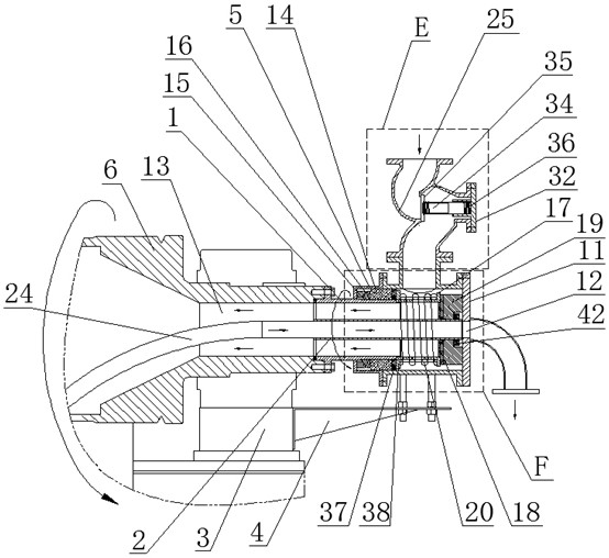
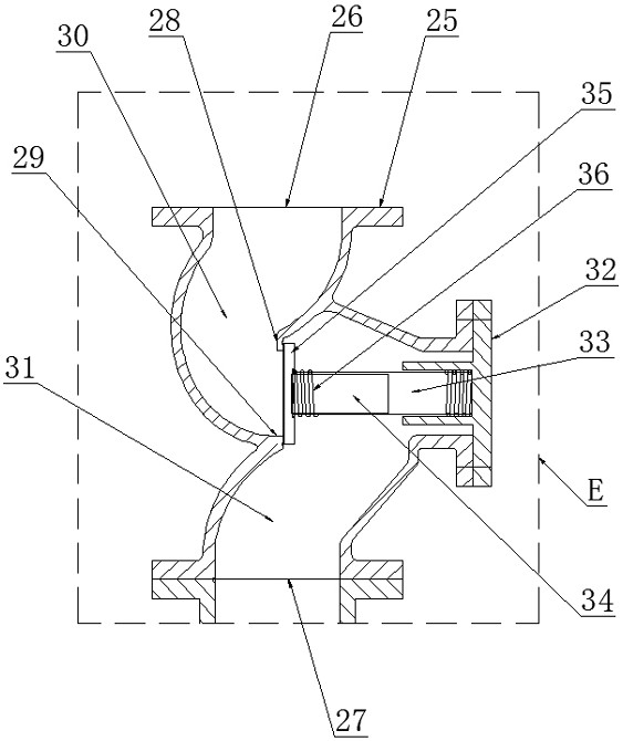
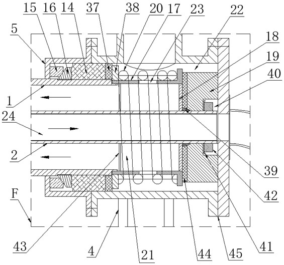
[0020] Such as figure 1 , figure 2 , image 3 , Figure 4As shown, the described high-temperature gas transmission and drainage mechanism includes: a rotating outer pipe 1, a fixed inner pipe 2, and a support frame 4 for fixed connection with the roller support 3, and the support frame 4 supports The inner hollow shell 5 is provided with a front mounting port 7 close to the roller 6, a rear mounting port 8 far away from the roller 6, and a steam inlet between the front mounting port 7 and the rear mounting port 8 on the shell 5. Port 9, a check mechanism is installed on the steam inlet 9 of the housing 5, the check mechanism can only allow high-temperature steam to flow into the housing 5 from the steam inlet 9 and not allow the high-temperatur...


PUM


Abstract

The mechanism comprises a shell, a one-way valve is installed at a steam inlet of the shell, an end cover is installed at a rear installation opening of the shell, the front end of a rotating outer pipe is fixed to the shaft end of a roller, the rear end of the rotating outer pipe is inserted into the shell and provided with an oilless bearing, and the outer wall of the rotating outer pipe, the oilless bearing and the inner wall of the shell form an installation cavity. A sealing static ring and a sealing moving ring are sequentially arranged in the mounting cavity from front to back; an annular spring seat is arranged in the shell on the rear side of the rotary outer pipe, the rotary outer pipe is sleeved with the front end of the spring seat, the fixed inner pipe is arranged in the rotary outer pipe and the spring seat in a penetrating mode, a thrust ring and a fixed ring are arranged on the outer portion of the fixed inner pipe from front to back, and a first spring is arranged on the outer portion of the spring seat; the first spring can push the oilless bearing and the sealing movable ring to move forwards along the rotating outer pipe till the sealing movable ring is in sealing contact with the sealing static ring all the time, a plurality of air inlet holes are formed in the outer circumferential wall of the spring seat in the circumferential direction, and a siphon is inserted into the fixed inner pipe. The roller heating device has the advantage of being good in roller heating effect.

Description

technical field [0001] The invention relates to the technical field of drying equipment, in particular to a high-temperature gas transmission and drainage mechanism in the drying equipment. Background technique [0002] Drying is to vaporize and escape the moisture (generally referring to water or other volatile liquid components) in the material by heating to obtain a solid material with a specified moisture content. The purpose of drying is to meet the needs of material use or further processing. Drying the harvested grains below a certain moisture content prevents mildew and ensures the safety of grain production. Sludge is dried into renewable energy for power generation in power plants. Sludge disposal has always been the focus of the water pollution prevention and control industry. After wet sludge is dried by a dryer, the dried sludge can be used as fuel for coal-fired power plants, which can not only Significantly reduce carbon dioxide emissions, and reduce product...

Claims


Application Information

Patent Timeline
Patent Type & Authority Applications(China)
IPC IPC(8): C02F11/13
CPCC02F11/13
Inventor 钟志良陈晓雷顾建清罗德彪魏树林
Owner 江苏龙净节能科技有限公司
Why Eureka
Try Eureka