
Novel automatic wire feeding device of splayed nail machine

A wire feeding device and a zigzag technology are applied in the field of auxiliary wire feeding devices of zigzag nail machines, which can solve problems such as hidden dangers, affect normal production, loose iron wires, etc., and achieve the effects of improving production efficiency, ensuring normal operation, and reducing hidden dangers to safety.

Pending Publication Date: 2022-03-15
安平县三兴金属丝网制造有限公司
View PDF0 Cites 2 Cited by
  • Summary
  • Abstract
  • Description
  • Claims
  • Application Information

AI Technical Summary

Problems solved by technology

[0002] As we all know, the eight-character nail machine is a machine that cuts the iron wire into a required length and bends it into a "eight" shape. The wire feeding device of the eight-character nail machine is an accessory device used to feed the iron wire for the eight-character nail machine. It has been widely used in the field of mechanical processing; the wire feeding of the existing eight-character nail machine generally directly places the coiled iron wire at the feeding end of the eight-character nail machine, and the end of the iron wire is conveyed by several guide wheels. For the wire feeding of the eight-character nail machine, because the eight-character nail machine works intermittently, the wire feeding is stopped after the iron wire is cut off, and then the wire feeding is continued after the bending of the iron wire is completed. This wire feeding method is easy to cause loose iron wire The situation of being entangled will affect the normal production, and the iron wire itself has a large internal stress, and it is easy to bounce off when it is squeezed, which has certain potential safety hazards.

Method used


Image

  • Novel automatic wire feeding device of splayed nail machine
  • Novel automatic wire feeding device of splayed nail machine
  • Novel automatic wire feeding device of splayed nail machine

Examples


Embodiment Construction

[0021] The following will clearly and completely describe the technical solutions in the embodiments of the present invention with reference to the accompanying drawings in the embodiments of the present invention. Obviously, the described embodiments are only some, not all, embodiments of the present invention. Based on the embodiments of the present invention, all other embodiments obtained by persons of ordinary skill in the art without making creative efforts belong to the protection scope of the present invention.

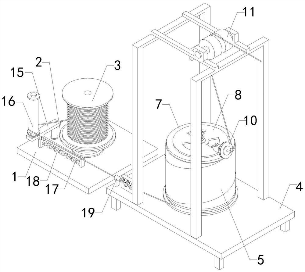
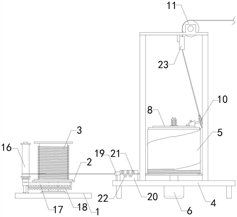
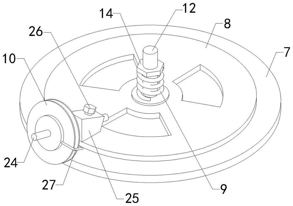
[0022] see Figure 1-4 , a new type of automatic wire feeding device for eight-character nailing machine of the present invention, including a wire feeding mechanism and a wire feeding mechanism, the wire feeding mechanism includes a base 1, and a turntable 2 is installed on the base 1 for rotation, and on the turntable 2 Iron wire feeder 3 is installed, and iron wire feeder 3 and turntable 2 are prior art, and iron wire feeder 3 is detachably installed on tur...


PUM


Abstract

The invention relates to the technical field of auxiliary wire feeding devices of splayed nailing machines, in particular to a novel automatic wire feeding device of a splayed nailing machine. The invention discloses a splayed nail machine which can effectively prevent iron wires from being loosened and wound together, guarantee normal operation of the splayed nail machine, reduce potential safety hazards and improve production efficiency, and comprises a wire feeding mechanism and a wire feeding mechanism, the wire feeding mechanism comprises a base, a rotating disc is rotationally installed on the base, an iron wire tray is installed on the rotating disc, and the wire feeding mechanism comprises a rack. An iron roller and a driving motor for driving the iron roller to rotate are arranged on the rack, a circular groove is formed in the top end of the iron roller, a brake drum is installed in the circular groove, a brake pad on the outer side of the brake drum makes contact with the inner side wall of the circular groove, an iron disc is arranged at the top end of the brake drum, a compression spring is installed at the top end of the iron disc, and a wire guide wheel is arranged on the outer side of an iron wire. A wire feeding wheel is arranged at the top end of the machine frame and located above the iron disc.

Description

technical field [0001] The invention relates to the technical field of an auxiliary wire feeding device for a figure eight nail machine, in particular to a novel automatic wire feeding device for a figure eight nail machine. Background technique [0002] As we all know, the eight-character nail machine is a machine that cuts the iron wire into a required length and bends it into a "eight" shape. The wire feeding device of the eight-character nail machine is an accessory device used to feed the iron wire for the eight-character nail machine. It has been widely used in the field of mechanical processing; the wire feeding of the existing eight-character nail machine generally directly places the coiled iron wire at the feeding end of the eight-character nail machine, and the end of the iron wire is conveyed by several guide wheels. For the wire feeding of the eight-character nail machine, because the eight-character nail machine works intermittently, the wire feeding is stopped...

Claims


Application Information

Patent Timeline
Patent Type & Authority Applications(China)
IPC IPC(8): B65H57/14B65H59/10B65H49/28
CPCB65H57/14B65H59/10B65H49/28
Inventor 田喜旺
Owner 安平县三兴金属丝网制造有限公司
Learn More