
Optical coherence elastic imaging auxiliary equipment for retina operation

An optical coherent and elastic imaging technology, which is applied in sanitary equipment for toilets, stereotaxic surgical instruments, cleaning methods using tools, etc., can solve problems such as affecting imaging results, increasing the workload of doctors, and being unable to fix the patient's head. , to avoid dust and avoid cross-infection

Inactive Publication Date: 2022-03-15
赵雁之
View PDF0 Cites 0 Cited by
  • Summary
  • Abstract
  • Description
  • Claims
  • Application Information

AI Technical Summary

Problems solved by technology

[0004] In order to overcome the shortcomings that the existing equipment cannot fix the patient's head, causing the patient's head to shake easily, affecting the imaging results, and requiring the doctor to manually sterilize the handle and increasing the doctor's workload, the purpose of the present invention is to provide a An optical coherent elastography auxiliary device for retinal surgery that reduces the workload of doctors and avoids the impact of imaging results

Method used


Image

  • Optical coherence elastic imaging auxiliary equipment for retina operation
  • Optical coherence elastic imaging auxiliary equipment for retina operation
  • Optical coherence elastic imaging auxiliary equipment for retina operation

Examples


Embodiment 1

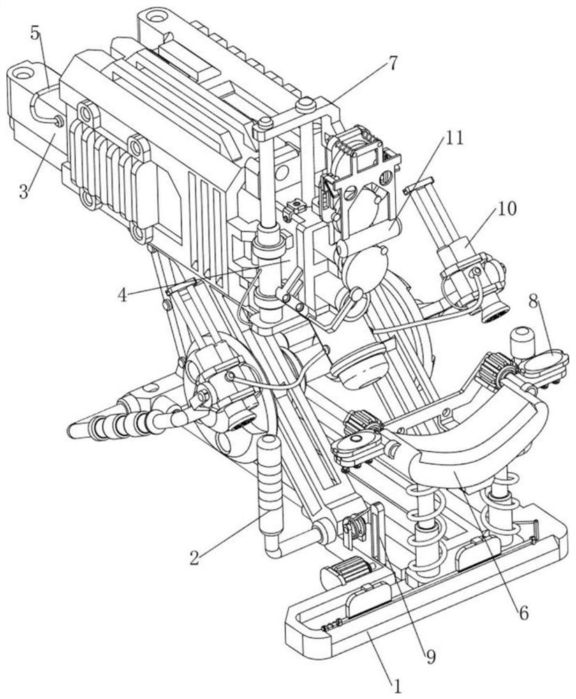
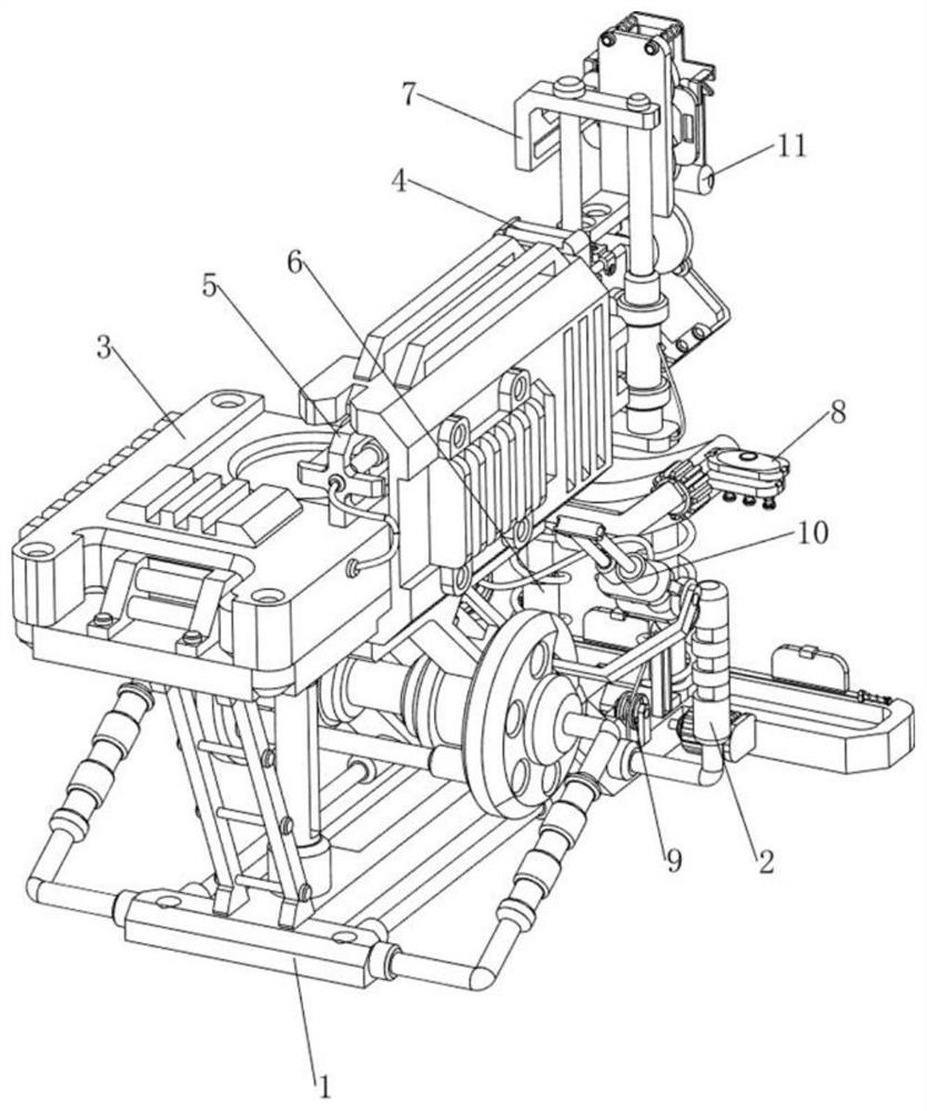
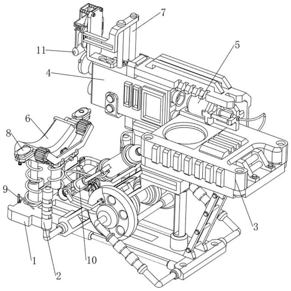
[0043] An optical coherent elastography aid for retinal surgery, such as Figure 1-22 As shown, it includes a fixed bracket 1, a fixed handle 2, a superluminescent light-emitting diode 3, an X-type fiber coupler 4, a detector 5, a support movement mechanism 6, and a lens focusing mechanism 7. The front side of the fixed bracket 1 is symmetrically arranged with fixed Handle 2, superradiant light-emitting diode 3 is arranged on the upper rear side of fixed bracket 1, X-type optical fiber coupler 4 is arranged on the upper part of fixed bracket 1, detector 5 is arranged on the left front side of superluminescent light-emitting diode 3, and fixed bracket 1 front side is provided with The supporting moving mechanism 6 is provided with a lens focusing mechanism 7 on the supporting moving mechanism 6 and the X-type optical fiber coupler 4 .

[0044] The support movement mechanism 6 includes a slide block 61, a telescopic post 62, a rubber bracket 63 and a first spring 64. The front s...


PUM


Abstract

The invention relates to auxiliary equipment, in particular to optical coherence elastic imaging auxiliary equipment for a retina operation. The invention aims to provide the optical coherence elastic imaging auxiliary equipment for the retina operation, which can reduce the workload of a doctor and prevent an imaging result from being influenced. According to the technical scheme, the optical coherence elastic imaging auxiliary equipment for the retina operation comprises a fixing support, fixing handles, a super-radiation light-emitting diode, an X-type optical fiber coupler, a detector, a supporting moving mechanism and a lens focusing mechanism, the fixing handles are symmetrically arranged on one side of the fixing support, the super-radiation light-emitting diode is arranged on the fixing support, and the X-type optical fiber coupler is arranged on the X-type optical fiber coupler. An X-type optical fiber coupler is arranged on one side of the fixing support, and a detector is arranged on one side of the super-radiation light-emitting diode. Output shafts of the first gear motor and the second gear motor drive a sponge cushion to rotate inwards, so that the sponge cushion clamps the head of the patient, and the phenomenon that the head of the patient shakes and affects the imaging result is avoided.

Description

technical field [0001] The invention relates to an auxiliary device, in particular to an optical coherent elastic imaging auxiliary device for retinal surgery. Background technique [0002] The retinal image of the human eye is an indispensable and important information in ophthalmology diagnosis and treatment. Real-time tracking of the topographic changes of the fundus retina will help the early diagnosis and prevention of physical diseases. At present, retinal imaging equipment applies confocal scanning technology to retinal imaging of living human eyes. The confocal vacuum pinhole at the detection end is used to shield the stray light from the non-focal plane of the sample, so as to obtain high-resolution images of the focal plane of the sample. However, the existing When the retinal imaging device is imaging the patient, because the patient's head is fixed in one direction and plane for a long time, the patient stabilizes himself by holding the handle on the device with ...

Claims


Application Information

Patent Timeline
Patent Type & Authority Applications(China)
IPC IPC(8): A61F9/00A61B90/14A61L2/22A61L2/26B08B1/00
CPCA61F9/00A61B90/14A61L2/22A61L2/26A61F2009/0035B08B1/143
Inventor 赵雁之黄国富
Owner 赵雁之
Learn More