
Lens device with shading structure

A shading structure and lens technology, applied in optics, installation, optical components, etc., can solve problems such as poor image quality, and achieve the effect of improving image quality and increasing practicability

Inactive Publication Date: 2021-07-02
CAL COMP BIG DATA INC
View PDF6 Cites 0 Cited by
  • Summary
  • Abstract
  • Description
  • Claims
  • Application Information

AI Technical Summary

Problems solved by technology

Also, the light from these bad angles is the reason for the poor quality of the captured images

Method used


Image

  • Lens device with shading structure
  • Lens device with shading structure
  • Lens device with shading structure

Examples


Embodiment Construction

[0052] The detailed description and technical content of the present invention are described below with the accompanying drawings, but the attached drawings are only for reference and illustration, and are not used to limit the present invention.

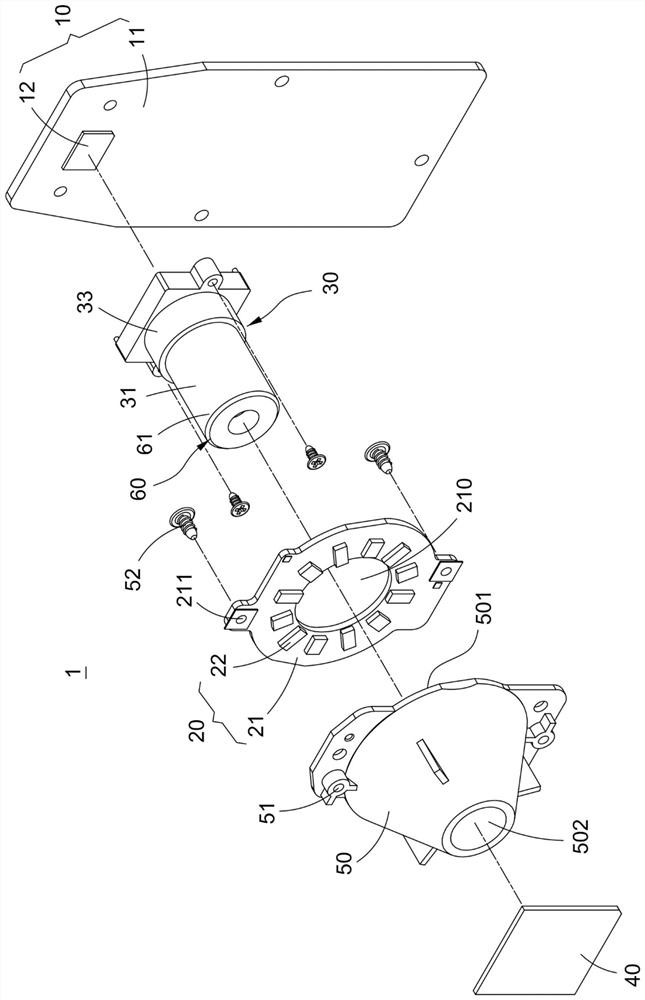
[0053] Please refer to image 3 and Figure 4 , are respectively a three-dimensional exploded schematic diagram and a combined cross-sectional view of the lens device with a light-shielding structure of the present invention. The present invention is a lens device 1 with a light-shielding structure, which includes a control module 10 , a light-emitting module 20 , a lens module 30 , a focusing lens 40 , a reflection sheet 50 and a light shield 60 . The control module 10 can control the operation of the light emitting module 20 , and receive light from the lens module 30 to perform calculations. Part of the light emitted by the light emitting module 20 will directly pass through the focusing lens 40 , and part of the light will pas...


PUM


Abstract

The invention relates to a lens device with a shading structure. A control module comprises a control circuit board and a photosensitive element; a light-emitting module comprises a light source circuit board and a light-emitting element which are electrically connected with the control circuit board; a lens module is arranged corresponding to the photosensitive element and comprises a lens barrel and a plurality of lenses; a focusing lens is arranged in front of the lens module; a reflector plate is arranged between the lens module and the focusing lens and can reflect light emitted by the light-emitting element to penetrate out of the focusing lens; and a light shield is connected with the lens barrel and extends outwards from the front edge of the lens barrel to form a light shield section which is used for shielding the light reflected by the reflector plate and preventing the light from directly entering the lens barrel, so that the light with a poor angle is prevented from entering the lens barrel to influence the image quality.

Description

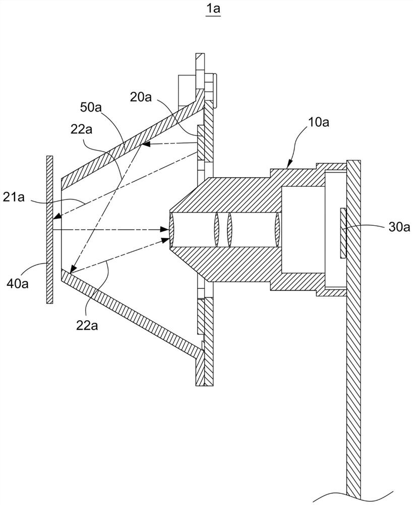
technical field [0001] The invention relates to a lens module, in particular to a lens device with a light-shielding structure. Background technique [0002] Generally, when a camera is in use, if strong light from a bad angle enters the lens, the quality of the captured image will be poor. If it is mild, it will cause light spots, and if it is severe, it will make the overall image blurry. In this regard, the current camera will install a hood in front of the lens to reduce the image quality damage caused by stray light during shooting, and to increase the color and saturation of the image. [0003] Furthermore, the commercially available skin quality testing equipment uses a lens module to take pictures of the skin to be tested at close range, and then analyzes the captured skin images, so as to know the physiological condition of the skin to be tested. Such as figure 1 As shown, the current lens device 1a used in skin quality testing instruments is mainly provided with ...

Claims


Application Information

Patent Timeline
Patent Type & Authority Applications(China)
IPC IPC(8): G03B11/04G03B15/02G03B15/06A61B5/00H04N5/225
CPCG03B11/04G03B15/02G03B15/06A61B5/0064A61B5/0077A61B5/441H04N23/55G02B7/021G02B5/12G03B15/05G03B2215/0575G03B2215/0567H04N23/56G03B17/02G02B7/04
Inventor 洪明华翁钜强
Owner CAL COMP BIG DATA INC
Learn More