


Quick Research
Generate reliable direction feasibility study reports for your R&D in just a few steps.

Technical Q&A
Discover and master advanced knowledge NOW. Basics, ideas, possibilities, all at once.

Find Solutions
As an expert in R&D theories, this can generate solutions to your technical problems instantly.

Evaluate Feasibility
Analyze your overall solution with one click, know your potential R&D risks in advance.

Monitor Landscape
Get weekly tech updates, stay abreast of the latest tech innovations and key insights.
Object surface roughness identification method, system and equipment
An object surface and recognition method technology, applied in the field of object recognition, can solve the problems that it is difficult to ensure that the selected features contain enough information and affect the accuracy of roughness recognition, so as to achieve intuitive signal features, avoid the introduction of invalid features, and avoid The effect of feature loss
- Summary
- Abstract
- Description
- Claims
- Application Information
AI Technical Summary
Problems solved by technology
Method used
Image

Examples
Embodiment 1
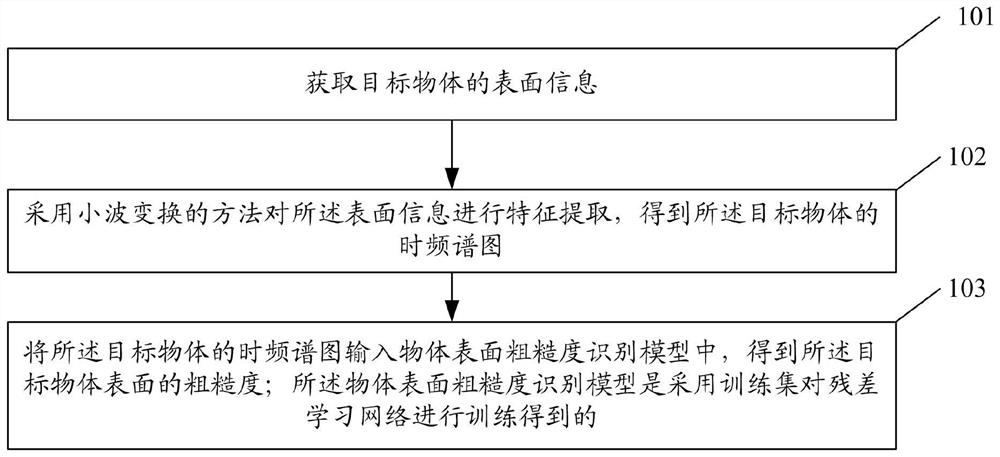
[0045]figure 1 A flow chart of an object surface roughness identification method provided in Example 1 of the present invention. See figure 1 , The surface roughness identification method of the object of the present embodiment, including:
[0046] Step 101: Get the surface information of the target object.
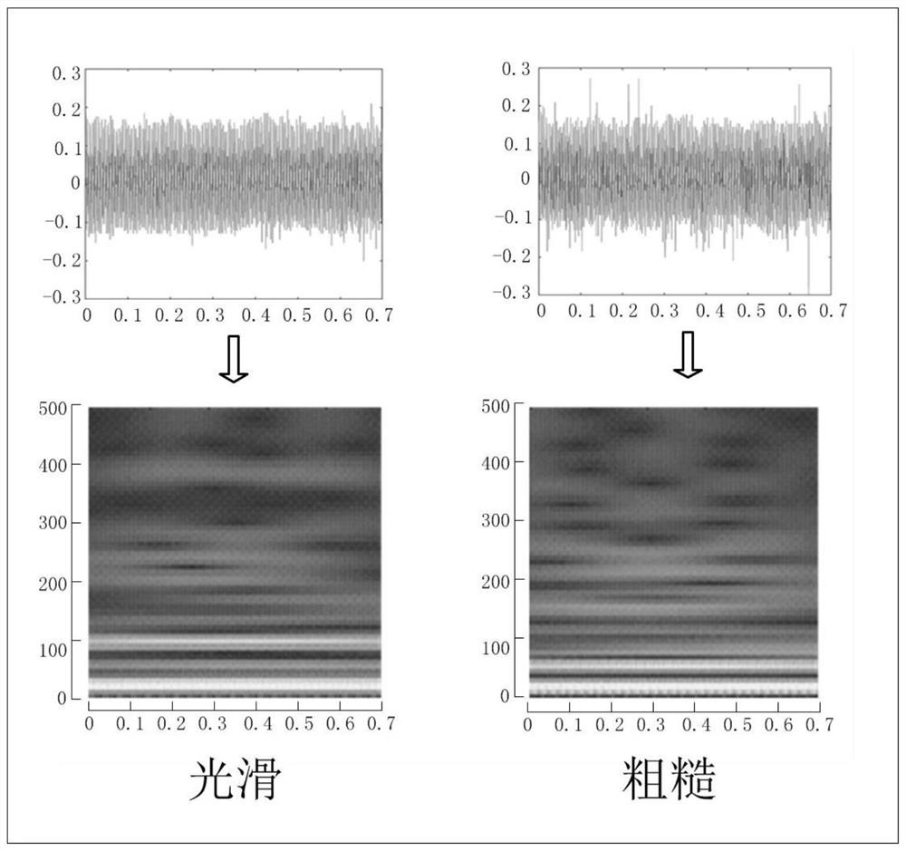
[0047] Step 102: A method of feature the surface information by means of a wavelet transform to obtain a time spectrogram of the target object.
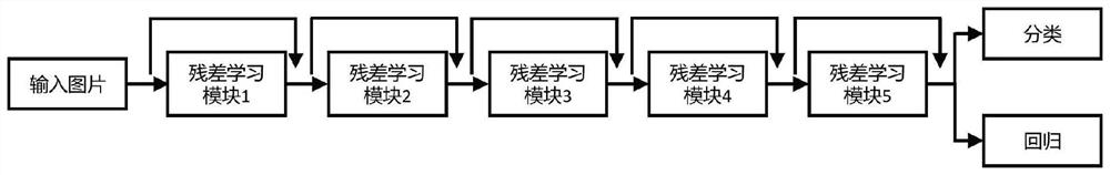
[0048] Step 103: In inputting the time spectrum of the target object, in the surface roughness recognition model of the object, the surface roughness of the target object is obtained; the surface roughness recognition model of the object is to train the residual learning network for the training set. owned.
[0049] In one example, step 101, including:
[0050] Touch the tactile sensor to contact the target object, collect and store the signal of the haptic sensor, i.e., surface information of the target object. Specifically, the ha...
Embodiment 2
[0082] This embodiment provides an object surface roughness recognition system, Figure 8 A structural diagram of an object surface roughness identification system provided in Example 2 of the present invention. See Figure 8 , The system, including:
[0083] The information acquisition module 201 is used to obtain surface information of the target object.
[0084] The feature extraction module 202 is used to extract the surface information by means of a wavelet transform to obtain a time spectrogram of the target object.
[0085] The roughness identification module 203 is configured to obtain a roughness of the surface roughness identification model of the target object to obtain a roughness of the surface roughness identification model of the target object; Poor learning networks are trained.
[0086] In one example, the feature extraction module 202 includes:
[0087] Time Frequency Domain Feature Extraction Unit, used to use discrete wavelet transform, and extract the time-frequ...
Embodiment 3
[0091] This embodiment provides a computer device. Figure 9 A structural diagram of a computer apparatus provided in Example 3 of the present invention. Figure 9 The displayed computer device 50 is merely an example and should not be restricted to the functions of the present embodiment. Such as Figure 9 As shown, the computer device 50 is manifested in the form of a general computing device. Components 50 can include, but are not limited to, one or more processors or processing units 500, memory 516, connected to a bus 501 of different system components (including memory 516 and processing unit 500). The memory 516 is configured to store a computer program that includes a program instruction; the processor is configured to call the program instruction to perform the object surface roughness identification method of Example 1.
[0092] Bus 501 represents one or more of several types of bus structures, including memory bus, memory controllers, peripheral bus, graphical acceleration...
PUM
 Abstract
Description
Claims
Application Information
 - R&D Engineer
- R&D Manager
- IP Professional
- Industry Leading Data Capabilities
- Powerful AI technology
- Patent DNA Extraction
Browse by: Latest US Patents, China's latest patents, Technical Efficacy Thesaurus, Application Domain, Technology Topic, Popular Technical Reports.
© 2024 PatSnap. All rights reserved.Legal|Privacy policy|Modern Slavery Act Transparency Statement|Sitemap|About US| Contact US: help@patsnap.com