Blade composite surface strengthening method

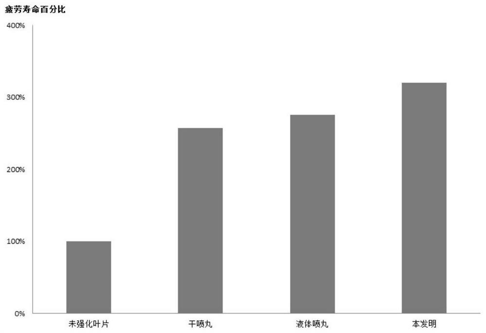
A composite surface and surface strengthening technology, applied in the field of surface strengthening, can solve problems such as insufficient surface roughness, large dispersion of blade surface residual stress, and insufficient blade fatigue life, etc., to achieve good surface residual compressive stress and roughness, Improved quality stability and high blade fatigue life

Pending Publication Date: 2022-03-11
中船重工龙江广瀚燃气轮机有限公司
View PDF0 Cites 0 Cited by
  • Summary
  • Abstract
  • Description
  • Claims
  • Application Information

AI Technical Summary

Problems solved by technology

[0004] The purpose of the present invention is to solve the problem of insufficient surface roughness, large dispersion of blade surface residual stress, and insufficient blade fatigue life after surface strengthening in the prior art, and to provide a blade composite surface strengthening method

Method used


Image

  • Blade composite surface strengthening method
  • Blade composite surface strengthening method
  • Blade composite surface strengthening method

Examples


Embodiment 1

[0031] A blade composite surface strengthening method, comprising the following steps:

[0032] Step 1: Pre-treatment of surface strengthening on all surfaces of blades by means of vibratory finishing;

[0033] Step 2: Clamp the blade for the first time, put the blade into the liquid shot blasting equipment, expose the blade body, transition fillet and edge plate, use the mixed grinding liquid of projectile and oil to hit the blade surface, and complete the blade body liquid Dismantle tooling after shot peening;

[0034] Step 3: Clean the blade to remove the oil stain attached to the surface of the blade after processing;

[0035] Step 4: Carry out the second clamping of the blade, put the blade into the dry shot blasting equipment, expose the tenon of the blade, and use the projectile to hit the surface of the blade;

[0036] Step 5: Carry out the third clamping of the blade, put the blade into the dry shot peening equipment, expose the blade body, transition fillet and edg...

Embodiment 2

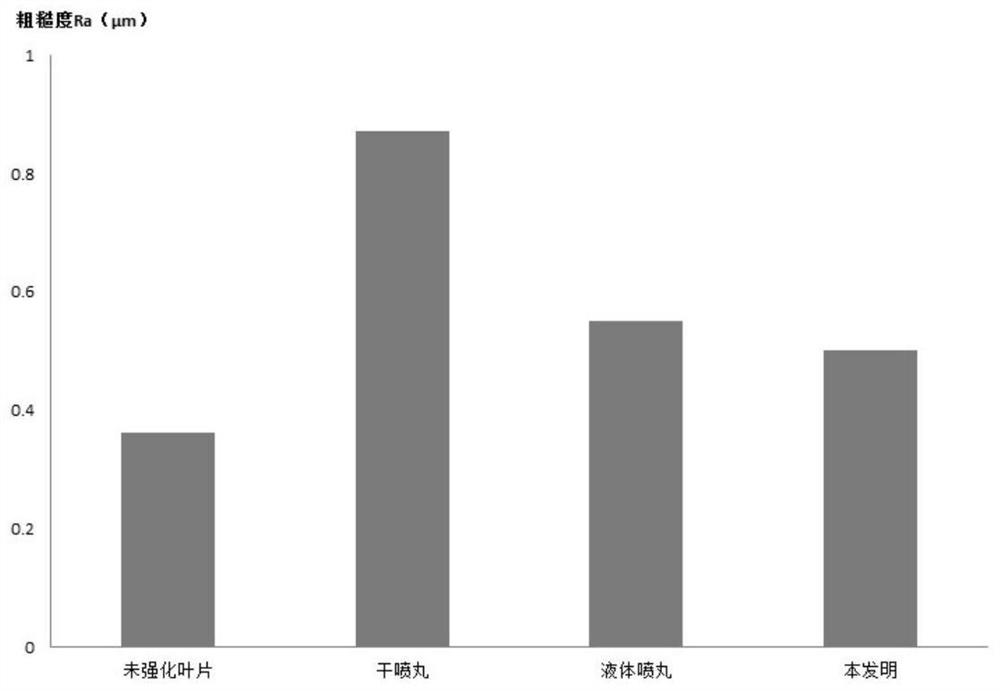
[0040] Further, in the step 1, after the surface strengthening pre-treatment is carried out on all surfaces of the blades by means of vibratory finishing, the surface roughness of the blades is checked, and the surface of the blades vibrating and brightening is not allowed to have residual machining traces and abrasive scratches. The surface roughness of the blade after vibrating polishing should satisfy Ra≤0.4μm.

Embodiment 3

[0042] Further, in the step 1 and step 6, alumina particles of different specifications are selected as the vibrating polishing abrasive, and the particle shapes include cylindrical, triangular prism, spherical, and ellipsoidal.


PUM

PropertyMeasurementUnit
Surface roughnessaaaaaaaaaa
Roughnessaaaaaaaaaa

Abstract

The invention belongs to the technical field of surface strengthening, and particularly relates to a blade composite surface strengthening method. The method comprises the steps of first-time vibration finishing, blade body liquid shot blasting, blade cleaning, tenon dry shot blasting, blade body dry shot blasting, second-time vibration finishing and the like. The problems that in the prior art, after surface strengthening, the surface roughness is not good enough, the blade surface residual stress dispersion degree is large, and the fatigue life of the blade is not good enough are solved. After the method is adopted for strengthening, the dispersion degree of residual stress on the surface of the blade is smaller, the residual stress layer depth is larger, the surface residual compressive stress and roughness are better, the fatigue life of the blade is longer, combination of multiple blade surface strengthening means is achieved, the quality stability of the blade is better improved, and the service life of the blade is prolonged. And the service life of the blades and the whole unit can be prolonged.

Description

technical field [0001] The invention belongs to the technical field of surface strengthening, and in particular relates to a blade composite surface strengthening method. Background technique [0002] During the service process of the blade, it is affected by the vibration force and centrifugal force of the unit, and operates in a high temperature and complex alternating load environment for a long time. The local stress and vibration caused by uneven force during the operation of the blade are the main reasons for the initiation and early growth of cracks on the surface of components. The expansion of cracks will eventually lead to fatigue failure of the blade and even the scrapping of the entire unit. Shot peening can effectively improve the fatigue life of the blade, thereby increasing the service life of the unit. [0003] At present, the dry shot peening process is easy to generate dust, which is harmful to human health; and the damage rate of the projectile is high an...

Claims


Application Information

Patent Timeline
IPC IPC(8): B24C1/10B24C9/00
CPCB24C1/10B24C9/00
Inventor 高硕邹献辉任大为张亮陶林赵强邢丽丹李洋杨成王鑫祁一东刘澎涛
Owner 中船重工龙江广瀚燃气轮机有限公司
Why Eureka
Try Eureka