
SQUID probe based on thin film bridge Josephson junction and use method thereof

A thin-film bridge, probe technology, applied in the size/direction of the magnetic field, the use of superconducting devices for magnetic field measurement, instruments and other directions, can solve the problems of limited spacing, large SQUID loop area, high temperature requirements, etc., to improve the magnetic field. Coupling strength, the effect of improving spatial resolution

Active Publication Date: 2022-03-08
SHANGHAI INST OF MICROSYSTEM & INFORMATION TECH CHINESE ACAD OF SCI
View PDF4 Cites 0 Cited by
  • Summary
  • Abstract
  • Description
  • Claims
  • Application Information

AI Technical Summary

Problems solved by technology

[0004] At present, the SQUID probes prepared on silicon wafers have the following disadvantages: first, in order to realize the gradiometer structure and offset the effect of the external field, the SQUID loop area is relatively large; secondly, the SQUID probes The needle is far away from the edge of the silicon wafer, which limits the distance between the SQUID capture flux loop and the sample in scanning applications, and cannot achieve precise distance control, thus limiting the spatial resolution of the scanning SQUID microscope; in addition, the conventional SQUID Most of the probes are prepared based on superconducting thin film Nb, and its maximum working temperature is around 6K, which requires high temperature of the sample, which is not conducive to the discovery of more novel physical phenomena

Method used


Image

  • SQUID probe based on thin film bridge Josephson junction and use method thereof
  • SQUID probe based on thin film bridge Josephson junction and use method thereof
  • SQUID probe based on thin film bridge Josephson junction and use method thereof

Examples


Embodiment Construction

[0055] Embodiments of the present invention are described below through specific examples, and those skilled in the art can easily understand other advantages and effects of the present invention from the content disclosed in this specification. The present invention can also be implemented or applied through other different specific implementation modes, and various modifications or changes can be made to the details in this specification based on different viewpoints and applications without departing from the spirit of the present invention.

[0056] see Figure 1 to Figure 6 . It should be noted that the diagrams provided in this embodiment are only schematically illustrating the basic idea of ​​the present invention, so that only the components related to the present invention are shown in the diagrams rather than the number, shape and Dimensional drawing, the type, quantity and proportion of each component may be changed according to actual needs during actual implement...


PUM

PropertyMeasurementUnit
widthaaaaaaaaaa
lengthaaaaaaaaaa

Abstract

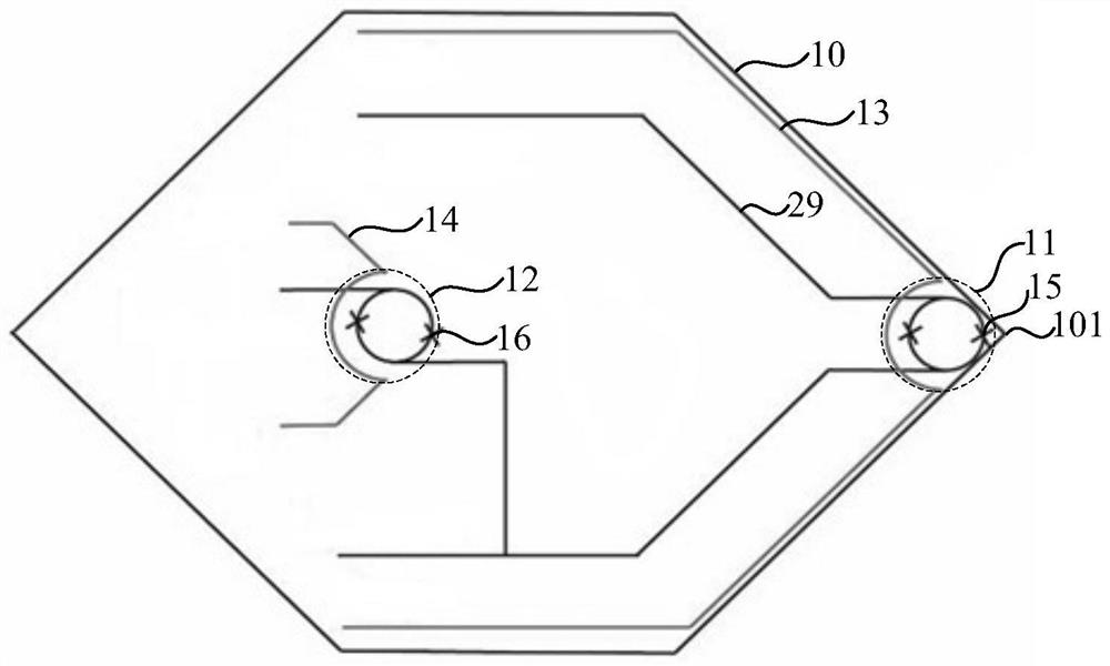
The invention provides a thin film bridge Josephson junction-based SQUID probe and a use method thereof, the structure comprises a silicon substrate, and one end of the silicon substrate is formed into a tip shape through a deep silicon etching technology; the device probe end comprises a first SQUID formed on the end where the tip shape of the silicon substrate is located; the device counteracting end comprises a second SQUID which is formed far away from the device probe end; and a first feedback coil and a second feedback coil. The SQUID probe is combined with a deep silicon etching technology to arrange a device probe end prepared on a silicon substrate at the tip-shaped end of the silicon substrate, so that the distance between the first SQUID and the edge of the tip of a silicon wafer can be accurately controlled, and the magnetic coupling strength of the SQUID and the surface of a sample is improved; in use, the SQUID probe structure can be combined with tuning fork resonance to realize accurate tip-sample distance control, so that the spatial resolution of the SQUID probe on the silicon substrate is greatly improved; in addition, multifunctional measurement of the probe can be realized by combining the first feedback coil and the second feedback coil integrated on the silicon substrate.

Description

technical field [0001] The invention relates to the field of superconducting quantum interference devices (SQUID), in particular to a SQUID probe based on a film bridge Josephson junction and a method for using the same. Background technique [0002] With the development of spintronics and superconducting electronics, studying the direct magnetic response of materials at the microscopic scale can reveal many properties that cannot be detected by other methods, such as observation of the magnetization relaxation process of nanoparticles, magnetic flux imaging in nanowires And flux quantization and eddy detection in superconductors. DC SQUID (Superconducting quantum interference devices) composed of two Josephson Junctions (JJ) connected in parallel is one of the most sensitive magnetic flux sensors known, and its detection sensitivity can approach the quantum limit. In microscopic magnetic imaging, the SQUID probe is combined with the SSM (Scanning SQUID Microscopy) composed...

Claims


Application Information

Patent Timeline
Patent Type & Authority Applications(China)
IPC IPC(8): G01R33/035
CPCG01R33/0354G01R33/0356
Inventor 潘银萍张登辉韩海龙曾俊文陈垒王镇
Owner SHANGHAI INST OF MICROSYSTEM & INFORMATION TECH CHINESE ACAD OF SCI
Learn More