
Method for realizing source control beam regulation and control of electromagnetic wave by using polarization confluence metasurface

A metasurface and electromagnetic wave technology, applied in the direction of electrical components, antennas, etc., can solve the problems that cannot meet the general beam control requirements and cannot work at the same time, and achieve the effects of anisotropy control, cost reduction and loss reduction

Pending Publication Date: 2022-03-04
CHONGQING UNIV
View PDF0 Cites 0 Cited by
  • Summary
  • Abstract
  • Description
  • Claims
  • Application Information

AI Technical Summary

Problems solved by technology

In another metasurface design method, the anisotropic metasurface can be used to realize the independent control of the orthogonal polarization. Although it can realize independent beam control under different incident wave states, the polarization of the outgoing wave is also positive. It cannot work at the same time, and the beam steering of this method can only realize the switching between a single state and two states, which cannot meet the general beam steering requirements.

Method used


Image

  • Method for realizing source control beam regulation and control of electromagnetic wave by using polarization confluence metasurface
  • Method for realizing source control beam regulation and control of electromagnetic wave by using polarization confluence metasurface
  • Method for realizing source control beam regulation and control of electromagnetic wave by using polarization confluence metasurface

Examples


Embodiment Construction

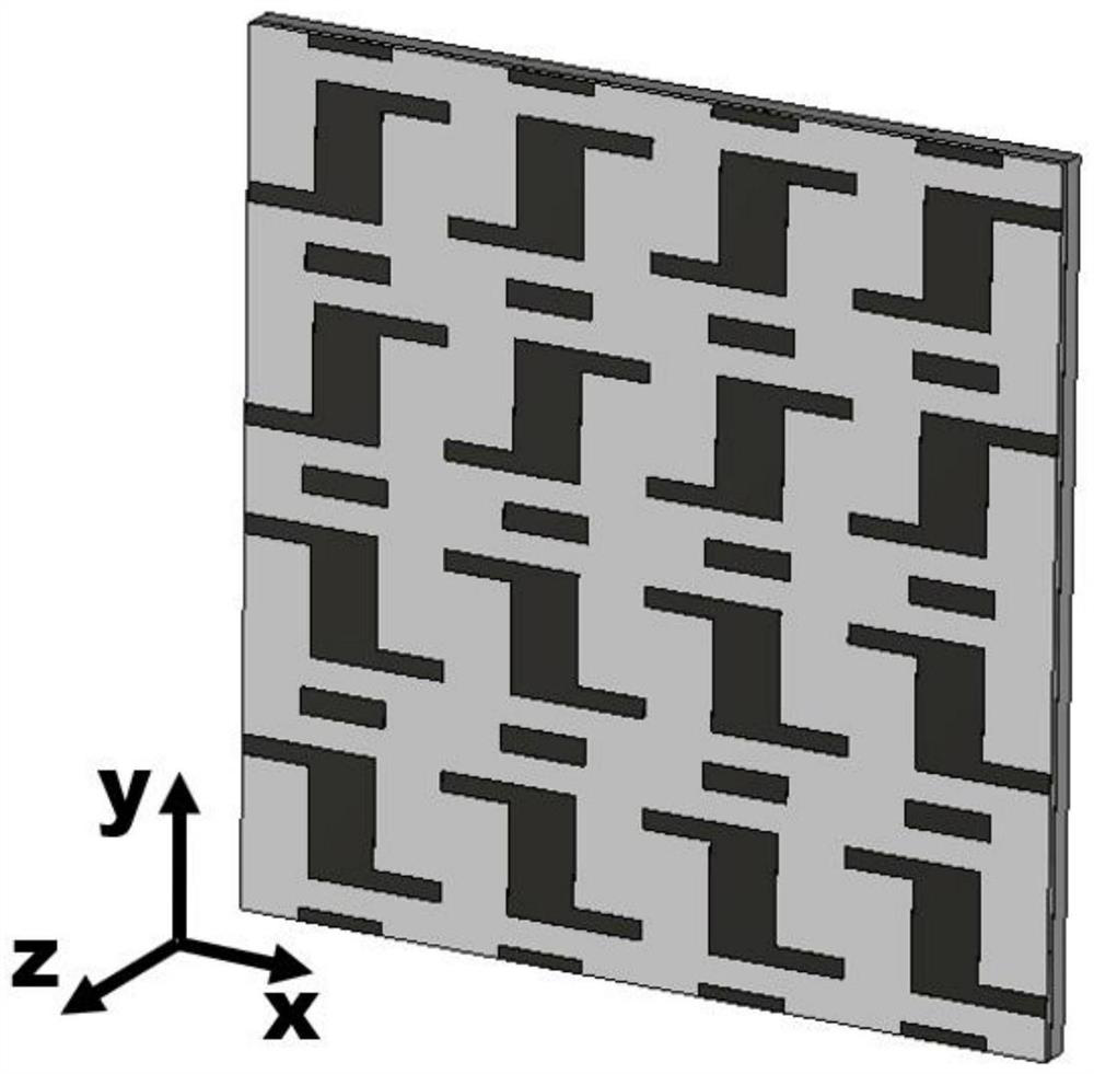
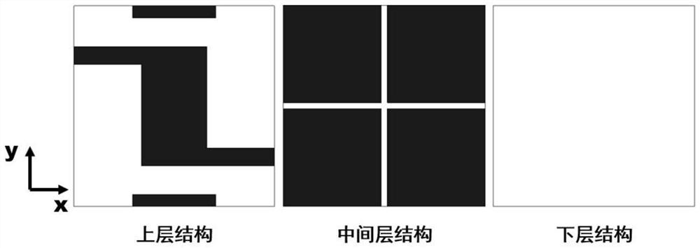
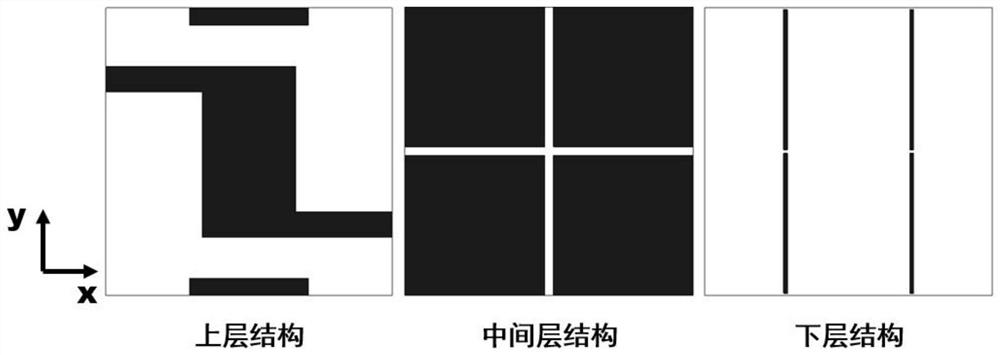
[0043] The present invention will be further described below in conjunction with the accompanying drawings and specific embodiments. A specific embodiment of the present invention is as figure 1 As shown, in the embodiment of the method for realizing the source-controlled beam control of electromagnetic waves by using the polarization confluence metasurface of the present invention, the metasurface is composed of 12*12 units, and along the y direction, the units of the metasurface are arranged as unit 1 , unit 2, unit 3 and unit 4, and the rest repeat this arrangement to form 12 unit distributions, and copy the above arrangement along the x direction to form a 12*12 metasurface.

[0044] The metasurface consists of a three-layer metal structure as a whole, the upper layer is the upper metal structure of the row-zero Jones matrix metasurface that regulates the transmitted wave, the middle layer is a metal backplane with cross gaps, and the dielectric constant between the two me...


PUM


Abstract

The invention discloses a method for realizing source control beam regulation and control of electromagnetic waves by using a polarization confluence metasurface. According to the method, the metasurface with a row zero Jones matrix is designed, energy synthesis of two orthogonal beam electromagnetic waves is achieved, and then beam pointing regulation and control of emergent waves of the metasurface under the condition of different feed sources are achieved. Compared with a traditional polarization conversion device design, the metasurface achieved through the method has the anisotropic polarization conversion characteristic, in other words, energy of one incident polarization is subjected to polarization conversion, and orthogonal incident polarization of the metasurface is emitted in the original polarization direction; compared with a traditional metasurface scanning mechanism which carries out beam regulation and control by regulating and controlling each unit, the method can realize the control of the radiation beam by using the feed source, thereby greatly reducing the attenuation of the metasurface, and reducing the cost and design difficulty of the metasurface. The anisotropic chiral metasurface unit structure adopted by the invention can realize the design of a row zero Jones matrix, and the symmetrical operation can realize the regulation and control of a polarization conversion component 1Bt phase, thereby realizing the source control beam scanning of electromagnetic waves.

Description

technical field [0001] The invention relates to the field of antenna (H05B6 / 72) and compound lens (G02B3 / 00), in particular to a method for realizing source-controlled beam regulation of electromagnetic waves by using a polarized confluence metasurface. Background technique [0002] Metasurface is a new type of technology that has emerged in recent years. As a two-dimensional form of metamaterials, it plays an increasingly important role in many scientific fields such as electromagnetism, optics, acoustics, and thermodynamics, and has become a research hotspot in these fields. The basic idea of ​​traditional metasurfaces is to adjust the structure of each unit on the metasurface, which also leads to the most serious drawbacks of metasurfaces: complex phase design and control, and large metasurface loss caused by phase control devices. Such problems severely restrict the development of metasurfaces. In another metasurface design method, the anisotropic metasurface can be use...

Claims


Application Information

Patent Timeline
IPC IPC(8): H01Q15/00H01Q15/24
CPCH01Q15/24H01Q15/0086
Inventor 孙志伟曹海林刘润龚鹤凌
Owner CHONGQING UNIV
Learn More