Steel-box-beam prefabricated slab and manufacturing method

A manufacturing method and prefabricated panel technology, applied in bridges, bridge construction, manufacturing tools, etc., can solve problems such as unguaranteed main reinforcement spacing, uniformity, and failure to meet design requirements, so as to improve construction efficiency and quality, reduce loss and cost , easy to promote the effect

Active Publication Date: 2017-09-01
JINAN URBAN CONSTR GRP
View PDF9 Cites 1 Cited by
  • Summary
  • Abstract
  • Description
  • Claims
  • Application Information

AI Technical Summary

Problems solved by technology

At present, in the process of making steel box girder prefabricated slabs, it is necessary to prefabricate the steel bars as a whole, and then place them in the finalized formwork. There are changes, and the line shape is disturbed and difficult to control, resulting in crossings between the main reinforcements at the end of the leakage, and the uneven spacing of the main reinforcements, which cannot meet the design requirements. The quality of the final prefabricated panels is difficult to guarantee and the construction efficiency is low. cost
In the current manufacturing technology, there is no measure to ensure the uniform spacing of the main ribs and the parallel leakage ends, and there are errors in the shape of the cast prefabricated slab

Method used


Image

  • Steel-box-beam prefabricated slab and manufacturing method
  • Steel-box-beam prefabricated slab and manufacturing method
  • Steel-box-beam prefabricated slab and manufacturing method

Examples


Embodiment Construction

[0031] In order to make the purpose, technical solutions and advantages of the embodiments of the present invention clearer, the technical solutions in the embodiments of the present invention will be clearly and completely described below in conjunction with the drawings in the embodiments of the present invention. Obviously, the described embodiments It is a part of embodiments of the present invention, but not all embodiments. Based on the embodiments of the present invention, all other embodiments obtained by those skilled in the art without creative efforts shall fall within the protection scope of the present invention.

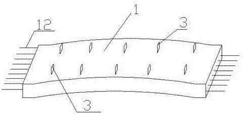
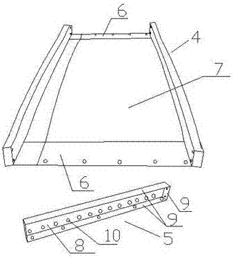
[0032] The steel box girder prefabricated panel of the present invention includes a steel mold in the prefabricated panel 1, and the prefabricated panel 1 is poured from the steel mold, and its shape conforms to the overall shape of the steel mold. Place the reinforcement cage 2 in the steel mold. There are several suspension rings 3 evenly fixed on the...


PUM


Abstract

The invention belongs to the technical field of municipal engineering construction, and particularly relates to a steel-box-beam prefabricated slab and a manufacturing method. The steel-box-beam prefabricated slab comprises a steel mold in the prefabricated slab. A steel reinforcement cage is placed in the steel mold, and a plurality of lifting rings are evenly fixed to both the left and the right sides of the steel reinforcement cage; the steel mold comprises a master mold and side molds which are fixed together through bolts, the side molds are fixed at both the front and the rear ends of the master mold, and steel reinforcement holes are evenly formed in vertical plates of the side molds; the steel reinforcement cage comprises an upper layer main reinforcement and a lower layer main reinforcement, the lower layer main reinforcement penetrates through the steel reinforcement holes of the side molds of the steel mold and extends out of the prefabricated slab, and the upper layer main reinforcement is located between the front and the rear side molds of the steel mold; and a stirrup binds the upper layer main reinforcement and the lower layer main reinforcement in a tendon pushing mode, the plane where the stirrup is located is parallel to the side molds, and the positions between the upper layer main reinforcement and the stirrup as well as between the lower layer main reinforcement and the stirrup are bound with binding wires.

Description

technical field [0001] The invention belongs to the technical field of municipal engineering construction, and in particular relates to a steel box girder prefabricated plate and its production. Background technique [0002] Prefabricated panels are an essential element of bridge engineering in municipal engineering, especially steel box girder prefabricated panels, which are widely used. At present, in the process of making steel box girder prefabricated slabs, it is necessary to prefabricate the steel bars as a whole, and then place them in the finalized formwork. There are changes, and the line shape is disturbed and difficult to control, resulting in crossings between the main reinforcements at the end of the leakage, and the uneven spacing of the main reinforcements, which cannot meet the design requirements. The quality of the final prefabricated panels is difficult to guarantee and the construction efficiency is low. cost. In the current manufacturing technology, ...

Claims


Application Information

Patent Timeline
IPC IPC(8): E01D19/00B28B23/02
CPCE01D19/00B28B23/02
Inventor 朱凌霄尹贻超张俊鲁孙素婷
Owner JINAN URBAN CONSTR GRP
Why Eureka
Try Eureka