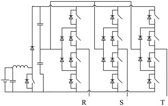
Three-phase inverter powered by overlapped double power supplies
A three-phase inverter, dual power supply technology, applied in the direction of conversion equipment without intermediate conversion to AC, conversion of AC power input into DC power output, electrical components, etc., can solve the problem of no adjustment, output filter reactor cost and The loss cannot be greatly reduced, the voltage is large, etc., to achieve the effect of increasing loss, cost and loss
- Summary
- Abstract
- Description
- Claims
- Application Information
AI Technical Summary
Problems solved by technology
Method used
Image
Examples
Embodiment 1
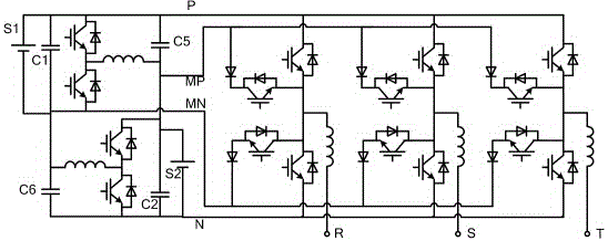
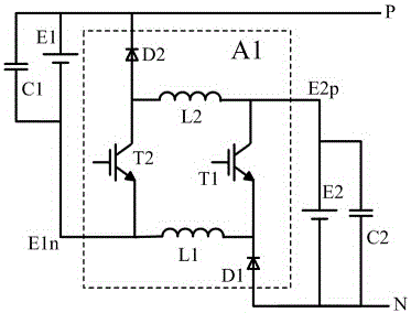
[0059] see image 3 and Figure 23 , a three-phase inverter powered by overlapping dual power supplies in this embodiment is composed of a front-stage conversion circuit, a rear-stage inverter circuit and an output filter.
[0060] The post-stage inverter circuit is a four-input post-stage inverter circuit B2. The four-input post-stage inverter circuit B2 is a three-phase inverter circuit with four input terminals on the DC side. The DC side connection line of the four-input post-stage inverter circuit B2 There are high-level line P, high-intermediate-level line MP, low-intermediate-level line MN, and low-level line N. Line MP, low intermediate level line MN, and low level line N supply power to the DC side of the rear-stage inverter circuit, and the three output terminals of the rear-stage inverter circuit are respectively connected to the three input terminals of the output filter F. The three output terminals of the stage inverter circuit B2 are: B2-a terminal, B2-b termi...
Embodiment 2
[0095] see image 3 and Figure 23 , the circuit structure of this embodiment is the same as that of Embodiment 1.
[0096] The mode of work characteristic of present embodiment is as follows:
[0097] Assume that the phase with the highest instantaneous voltage of the three-phase load is the H phase, the phase with the lowest instantaneous voltage is the L phase, and the phase with the intermediate instantaneous voltage is the M phase, V PN is the voltage difference between the high-level line P and the low-level line N. In this embodiment, at least one of the following working modes is used for at least 50% of a power frequency cycle:
[0098] (1) Adjust the voltage of the high-middle level line MP through the third pre-stage circuit A3, so that the voltage of the high-middle level line MP is biased towards the high-level line P, that is, the voltage of the high-level line P and the high-middle level line MP Voltage difference V PMP PN / 2, or / and adjust the voltage of th...
PUM
 Abstract
Description
Claims
Application Information
 - R&D Engineer
- R&D Manager
- IP Professional
- Industry Leading Data Capabilities
- Powerful AI technology
- Patent DNA Extraction
Browse by: Latest US Patents, China's latest patents, Technical Efficacy Thesaurus, Application Domain, Technology Topic, Popular Technical Reports.
© 2024 PatSnap. All rights reserved.Legal|Privacy policy|Modern Slavery Act Transparency Statement|Sitemap|About US| Contact US: help@patsnap.com


