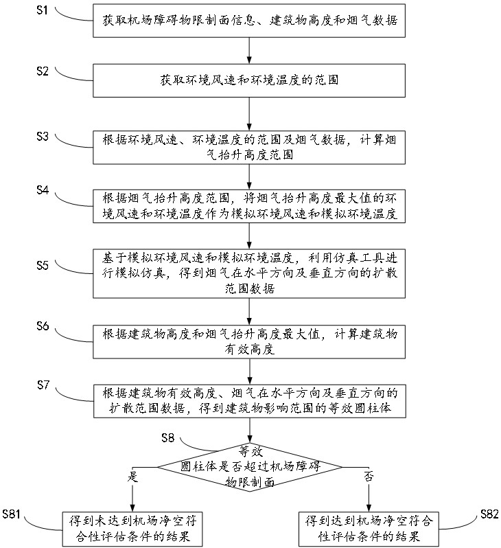
Airport clearance assessment method for flue gas emission obstacles
A smoke emission and obstacle technology, applied in the field of aviation safety, can solve the problems of inability to make flight safety assessments
- Summary
- Abstract
- Description
- Claims
- Application Information
AI Technical Summary
Problems solved by technology
Method used
Image

Examples
Embodiment 1
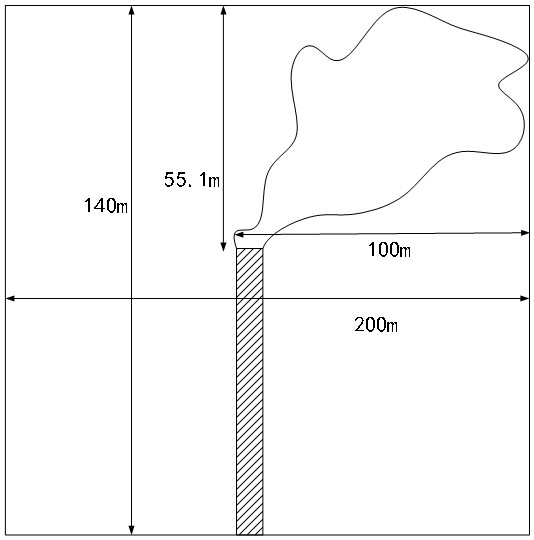
[0130] Evaluate the flue gas emission of No. 1 building. Since No. 1 building has not been put into operation and is still in the construction design stage, there is no measured data of flue gas outlet temperature and flue gas outlet velocity. Therefore, the data adopts the analog method and takes conservative values for calculation. Combined with relevant test reports, theoretical calculation, simulation and evaluation of flue gas and water vapor, the temperature Ts of the flue gas at the flue gas outlet is 72°C, that is, 345.15K. According to the building number 1, the height of the exhaust pipe is 80m, the inner diameter of the exhaust pipe is 4.6m, and the exit velocity of the flue gas is, ν s Take 8m / s.
[0131] When determining the range of ambient wind speed and ambient temperature, the average wind speed at a height of 10 meters above the ground in the last 5 years is obtained by querying the local meteorological data over the years It is 1.8 m / s, and the ambien...
Embodiment 2
[0142] Evaluate the flue gas emission of No. 5 building. Since No. 5 building has not been put into operation and is still in the construction design stage, there is no measured data of flue gas outlet temperature and flue gas outlet velocity. Therefore, the data adopts the analog method and takes conservative values for calculation. Combined with relevant test reports, theoretical calculation, simulation and evaluation of flue gas and water vapor, the temperature Ts of the flue gas at the flue gas outlet is 72°C, that is, 345.15K. According to the building number 5, the height of the exhaust pipe is 85m, the inner diameter of the exhaust pipe is 4.4m, and the exit velocity of the flue gas is, ν s Take 8m / s.
[0143] When determining the range of ambient wind speed and ambient temperature, the average wind speed at a height of 10 meters above the ground in the last 5 years is obtained by querying the local meteorological data over the years It is 1.8 m / s, and the ambien...
PUM
 Abstract
Description
Claims
Application Information
 - Generate Ideas
- Intellectual Property
- Life Sciences
- Materials
- Tech Scout
- Unparalleled Data Quality
- Higher Quality Content
- 60% Fewer Hallucinations
Browse by: Latest US Patents, China's latest patents, Technical Efficacy Thesaurus, Application Domain, Technology Topic, Popular Technical Reports.
© 2025 PatSnap. All rights reserved.Legal|Privacy policy|Modern Slavery Act Transparency Statement|Sitemap|About US| Contact US: help@patsnap.com