Laser light source and photoelectron microscope

A photoelectron microscope, laser light source technology, applied in microscopes, lasers, laser parts, etc., can solve the problem of stopping the laser device, and achieve the effects of suppressing absorption, improving measurement throughput, and reducing thermal load

Pending Publication Date: 2022-03-01
THE UNIV OF TOKYO +1
View PDF1 Cites 0 Cited by
  • Summary
  • Abstract
  • Description
  • Claims
  • Application Information

AI Technical Summary

Problems solved by technology

As a result, there is a problem that the resonator cannot oscillate and emit the second laser light, causing the laser device to stop

Method used


Image

  • Laser light source and photoelectron microscope
  • Laser light source and photoelectron microscope
  • Laser light source and photoelectron microscope

Examples


Embodiment Construction

[0022] (1) Regarding the photoelectron microscope using the laser light source according to the embodiment of the present invention

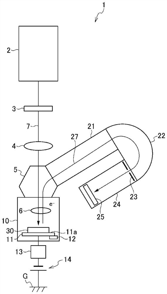
[0023] The laser light source of this embodiment is used as a light source for a photoelectron microscope. below, to be used as figure 1 The case of the light source of the photoelectron microscope 1 shown is taken as an example, and the laser light of this embodiment will be described. In addition, the photoelectron microscope 1 described below is an example of a photoelectron microscope, and various changes may be made to the configuration of the photoelectron microscope 1 . In addition, the laser light source according to the embodiment of the present invention can also be used as a light source of another photoelectron microscope.

[0024] First, the overall configuration of the photoelectron microscope 1 will be described. Such as figure 1 As shown, a photoelectron microscope 1 has a laser light source 2, a wavelength plate 3, an illumi...


PUM

PropertyMeasurementUnit
wavelengthaaaaaaaaaa

Abstract

The invention provides a laser light source with high energy and high output and a photoelectron microscope using the laser light source. A laser light source (2) for a photoelectron microscope for emitting quasi-continuous wave laser light (7) is provided with: a first laser light source (100) for emitting continuous wave coherent light (100a); an optical resonator (110) having an optical path for circulating the continuous wave coherent light (100a) and a nonlinear optical element (114) disposed on the optical path; and a quasi-continuous-wave light source (120) that emits quasi-continuous-wave coherent light (120a) having a shorter wavelength than the continuous-wave coherent light (100a) and an approximately rectangular output waveform, and when the quasi-continuous-wave coherent light (120a) is incident on the nonlinear optical element (114) from outside the optical resonator (110) in a state in which the continuous-wave coherent light (100a) is incident on the optical resonator (110) and circulates in an optical path, the quasi-continuous-wave light source (120) emits quasi-continuous-wave coherent light (120a). Quasi-continuous wave laser light (7) having a shorter wavelength than the quasi-continuous wave coherent light (120a) is emitted from the nonlinear optical element (114).

Description

technical field [0001] The invention relates to a laser light source and a photoelectron microscope. Background technique [0002] There is known a photoelectron microscope that irradiates a sample with high-energy laser light as excitation light, detects photoelectrons released from the sample, and forms an image. A photoelectron microscope is an electron projection type microscope that magnifies and images photoelectrons released from a substance by irradiating excitation light. The technique is used for chemical mapping and magnetic imaging of materials, resulting in a spatial resolution of about 20 nm. In particular, if excitation light with photon energy greater than the work function is used as the excitation light, a contrast strongly dependent on the magnitude of the work function can be obtained, and conductivity, valence, crystallinity, magnetism, etc. can be visualized. [0003] In this way, the photoelectron microscope is a device capable of two-dimensionally v...

Claims


Application Information

Patent Timeline
Patent Type & Authority Applications(China)
IPC IPC(8): H01S3/10H01S3/136H01S3/00G02F1/37G02B21/06G01N23/227
CPCH01S3/10H01S3/0071H01S3/136G02B21/06G02F1/37G01N23/227H01S3/00G02F1/353G01N2223/073G01N2223/33
Inventor 辛埴谷内敏之今井信一藤浦和夫古川保典
Owner THE UNIV OF TOKYO
Why Eureka
Try Eureka