
Method for manufacturing sealing gasket

A manufacturing method and technology for gaskets, which are used in the manufacture of final products, engine sealing, sealing/supporting devices, etc., can solve problems such as difficulty in forming shape and size, uneven film thickness, and difficulty in the distance between the front end of the nozzle and the substrate. Dimensionally stable effect

Pending Publication Date: 2022-03-01
NOK CORP
View PDF6 Cites 0 Cited by
  • Summary
  • Abstract
  • Description
  • Claims
  • Application Information

AI Technical Summary

Problems solved by technology

In the case of injection molding, there is an advantage that the shape of the gasket can be stabilized, but on the other hand, it is necessary to countermeasure against burrs, and there is a disadvantage that molds are required for products with different sizes and shapes.
In the case of screen printing, there are advantages such as a large degree of freedom in material selection and excellent maintenance, but on the other hand, there are disadvantages such as the shape of the gasket is unstable and it is difficult to obtain the desired shape.
In the case of using a dispenser, there are advantages such as a large degree of freedom in material selection. On the other hand, since the material is continuously applied while in contact with the substrate (separator body), the warping of the substrate Due to the influence of bending and positioning accuracy, it is difficult to keep the distance between the nozzle tip and the substrate constant, resulting in uneven film thickness.
Furthermore, in the case of using a dispenser, when forming the ring-shaped gasket, the part where the start side and the end side meet overlaps in double layers, so there is a disadvantage that it is difficult to form the desired shape and size.
[0003] In addition, there is also a study to adopt the inkjet method. In the case of this method, the viscosity of the material is low as the use condition, and there is a problem that it is difficult to apply liquid rubber as a material for the gasket.

Method used


Image

  • Method for manufacturing sealing gasket
  • Method for manufacturing sealing gasket
  • Method for manufacturing sealing gasket

Examples


Embodiment Construction

[0030] Hereinafter, the specific embodiment will be described in detail based on examples with reference to the drawings. However, unless otherwise specified, dimensions, materials, shapes, relative arrangements, and the like of components described in this embodiment are not intended to limit the scope of the present invention to these only.

[0031] (Example)

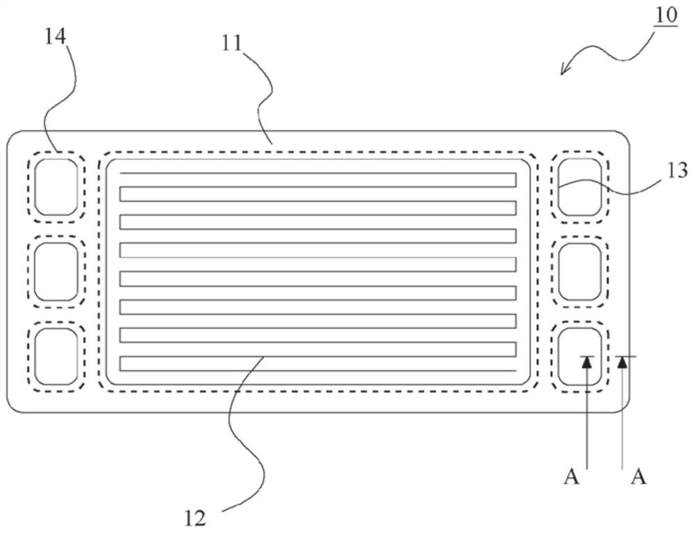
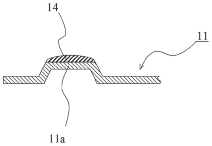
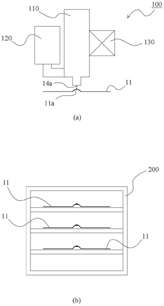
[0032] refer to Figure 1 to Figure 6 , the method of manufacturing the gasket according to the embodiment of the present invention will be described. In this embodiment, as an example, a case where a gasket is formed in a separator main body in a fuel cell will be described. However, the method of manufacturing the gasket in the present invention is not limited to the case of a separator, but can also be applied to a case where a rubber gasket is integrally provided with a metal gasket, for example.

[0033] figure 1 It is a plan view of the separator of the fuel cell. figure 2 is a cross-sectional view of the ...


PUM

PropertyMeasurementUnit
viscosityaaaaaaaaaa
viscosityaaaaaaaaaa
viscosityaaaaaaaaaa

Abstract

The invention provides a manufacturing method of a sealing gasket. The size and the shape of the sealing gasket can be stabilized without a mold. The gasket manufacturing method is characterized in that the gasket manufacturing method comprises a step of discharging liquid rubber onto a base material through a discharging device (100) and a step of forming a rubber gasket on the base material by solidifying the discharged liquid rubber, and the discharging device (100) is provided with a valve body (111) and a discharging port (114). The non-contact discharge device is a non-contact discharge device in which a discharge port (114) is used in a non-contact state with respect to the base material, the valve element (111) opens and closes a flow path through which liquid rubber flows, and the discharge port (114) discharges liquid rubber in a droplet form discontinuously by opening and closing the valve by the valve element (111).

Description

technical field [0001] The present invention relates to a method for manufacturing a gasket that forms a gasket on a base material. Background technique [0002] As a method of forming a gasket on a separator of a fuel cell, there are a method by injection molding, a method by screen printing, a method using a dispenser, and the like. In the case of injection molding, there is an advantage that the shape of the gasket can be stabilized, but on the other hand, measures against burrs are required, and there are disadvantages that molds are required for products with different sizes and shapes. In the case of screen printing, there are advantages such as a large degree of freedom in material selection and excellent maintainability, but on the other hand, there are disadvantages such as the shape of the gasket is unstable and it is difficult to obtain a desired shape. In the case of using a dispenser, there are advantages such as a large degree of freedom in material selection....

Claims


Application Information

Patent Timeline
Patent Type & Authority Applications(China)
IPC IPC(8): B05D1/26B05D7/24B05C5/02H01M8/0276
CPCB05D1/26B05D7/24B05C5/0225H01M8/0276Y02E60/50Y02P70/50B05D3/0272B05D2530/00F16J15/108B05C5/0237H01M8/0286H01M8/0271B05C5/02B05C11/1002F16J15/14B05C11/1034
Inventor 水泽誉三浦正広后藤教之中畑雄史
Owner NOK CORP
Learn More