Standardized complete equipment for mechanical connection of reinforcing steel bars
A technology of mechanical connection and complete set of devices, which is applied in the direction of structural elements, building components, building reinforcements, etc., can solve the problems of short steel bar connection length, small space for steel bar joints, and heavy welding workload, etc. The steel bar is short or other defects, the connection effect is good, and the effect is good
- Summary
- Abstract
- Description
- Claims
- Application Information
AI Technical Summary
Problems solved by technology
Method used
Image
Examples
Embodiment 1
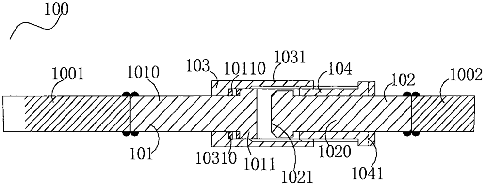
[0029] as attached figure 1 As shown, a standardized complete set of equipment 100 for mechanically connecting steel bars when the steel bars to be connected is difficult to rotate freely, generally speaking, it is a complete set of standardized connection joints, which are respectively connected to the steel bars: the ends of the connecting steel bars 1001 and 1002, and It includes a first component 101 and a second component 102 respectively connected to the end of the external reinforcement member by welding, a third component 103 and a fourth component 104 respectively mechanically connected to the component 101 and the second component 102, the first component Including the long screw rod 1010 of the first assembly, one end of the long screw rod 1010 of the first assembly is provided with a thick head-T-shaped end 1011, and the inside of both ends of the T-shaped end of the T-shaped end 1011 can be provided with a third assembly 103 engages and holds the T-shaped terminal...
Embodiment 2
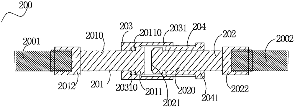
[0038] Such as figure 2 As shown, the standardization complete set of equipment 200 for mechanically connecting steel bars is respectively connected to the ends of the connecting steel bar 2001 and the connecting steel bar 2002. 202. A third component 203 and a fourth component 204 that are mechanically connected to the component 201 and the second component 202 respectively, the first component 201 includes a long screw 2010 of the first component, and one end of the long screw 2010 of the first component is provided with Pier thick head-T-shaped end 2011, the inside of both ends of the T-shaped end of the T-shaped end 2011 can be provided with a T-shaped end card slot 20110 that is engaged and held by the third component 203, and the long screw rod of the first component The other end of 2010 is provided with the first component long screw concave connection groove 2012 that is threadedly connected with the connecting steel bar 2001; the second component 202 includes the se...
Embodiment 3
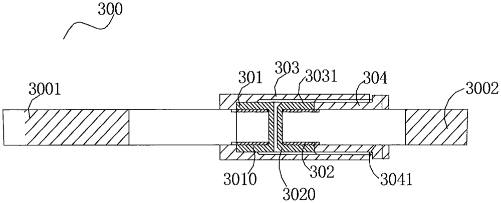
[0046] Such as image 3 As shown, the standardization complete set of equipment 300 for mechanically connecting steel bars is respectively connected to the ends of the connecting steel bar 3001 and the connecting steel bar 3002. 302. The third component 303 and the fourth component 304 are mechanically connected to the component 301 and the second component 302 respectively, the first component 301 includes a first component nut 3010, and the first component nut 3010 is connected to the connecting steel bar 3001 The end of the connecting steel bar 3001 is threaded, and the end of the connecting steel bar 3001 is thread rolled; the second assembly 302 includes a second assembly nut 3020, and the second assembly nut 3020 is threadedly connected to the end of the connecting steel bar 3002 , the end of the connecting steel bar 3002 is processed by thread rolling; the third component 303 includes an internally threaded sleeve 3031, and the internally threaded sleeve 3031 is sleeved...
PUM
 Abstract
Description
Claims
Application Information
 - R&D
- Intellectual Property
- Life Sciences
- Materials
- Tech Scout
- Unparalleled Data Quality
- Higher Quality Content
- 60% Fewer Hallucinations
Browse by: Latest US Patents, China's latest patents, Technical Efficacy Thesaurus, Application Domain, Technology Topic, Popular Technical Reports.
© 2025 PatSnap. All rights reserved.Legal|Privacy policy|Modern Slavery Act Transparency Statement|Sitemap|About US| Contact US: help@patsnap.com


