
Driving signal generation method and system of solid-state power amplifier

A driving signal, solid-state power technology, applied in power amplifiers, amplifiers, components of amplifying devices, etc., can solve the problems of affecting the service life of each device, harsh triggering conditions, and frequent actions of latching protection, so as to improve work efficiency. and device lifetime, reducing power consumption, and reducing the number of triggers

Inactive Publication Date: 2022-02-25
浩泰智能(成都)科技有限公司
View PDF6 Cites 0 Cited by
  • Summary
  • Abstract
  • Description
  • Claims
  • Application Information

AI Technical Summary

Problems solved by technology

[0004] Existing solid-state power amplifiers are usually equipped with a drive signal detection module, which detects the pulse width and pulse-off charge of the drive signal generated by the signal source, and directly inputs the qualified signal into the solid-state power device to trigger the action. The driving signal will immediately block the entire driving signal generation circuit to play a protective role; the disadvantage of this method is that as long as the driving signal is a little abnormal, it will trigger blocking and affect the working efficiency of the power amplifier; the trigger condition of blocking protection is too strict, and blocking The protection is easy to operate frequently, which increases the energy consumption of the solid-state power amplifier and affects the service life of each device

Method used


Image

  • Driving signal generation method and system of solid-state power amplifier
  • Driving signal generation method and system of solid-state power amplifier
  • Driving signal generation method and system of solid-state power amplifier

Examples


Embodiment 1

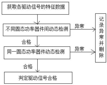
[0070] Such as figure 1 As shown, the present embodiment provides a method for generating a drive signal for a solid-state power amplifier, comprising steps:

[0071] Step 1: make the signal source always synchronously send out the driving signals of each solid-state power device;

[0072] Step 2: Perform dynamic process detection on all driving signals;

[0073] Within one cycle: when an abnormal driving signal is detected, delete all driving signals in this cycle and feed back the abnormal amount and abnormal driving signal to the signal source, and enter step 3; otherwise, determine the qualified driving signal and enter step 4;

[0074] Step 3: The signal source adjusts the abnormal drive signal according to the abnormal amount, and then re-sends the drive signal of each solid-state power device, and returns to step 2;

[0075] Step 4: Continuously output qualified drive signals to each solid-state power device before receiving the termination generation signal.

[007...

Embodiment 2

[0102] This embodiment provides a driving signal generating system for a solid-state power amplifier, which is constructed based on the method described in the previous embodiment, including: a signal source, a signal detection unit, a feedback unit, and a pre-stored output unit;

[0103] The signal source is used to send driving signals for each solid-state power device;

[0104] The signal detection unit is used to perform dynamic process detection on all driving signals. When an abnormal driving signal is detected, all driving signals in the period are deleted, and the feedback unit feeds back the abnormal amount and the abnormal driving signal to the signal source. The signal The detection unit also sends qualified driving signals to the pre-stored output unit;

[0105] The signal source is also used to adjust the abnormal drive signal according to the abnormal amount and then resend the drive signal of each solid-state power device;

[0106] The pre-storage output unit c...

Embodiment 3

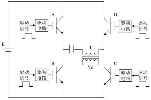
[0119] This embodiment is based on the above-mentioned embodiments to generate a driving signal for a solid-state power amplifier, such as image 3 As shown, the solid-state power amplifier in this embodiment is composed of solid-state power device A, solid-state power device B, solid-state power device C and solid-state power device D to form an H-bridge amplifier. The turn-on and turn-off of the device is output to the load through the transformer, and the transformer also plays the role of impedance transformation. In order to prevent the loss of the DC component to the transformer, an isolation capacitor is set.

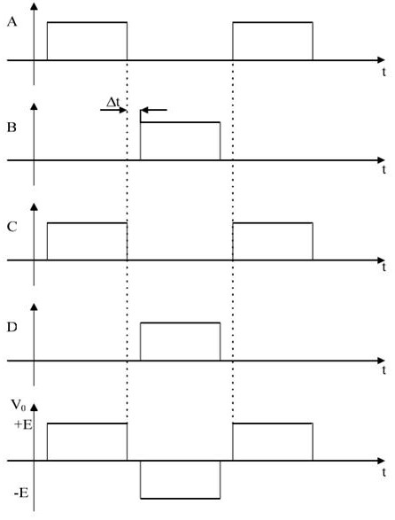
[0120] Figure 4 is the working waveform diagram of the solid-state power amplifier, Δt is the dead time, according to Figure 4 The data standard of the waveform chart sets the duty cycle threshold, preset delay threshold, pulse width threshold and phase threshold in dynamic process detection. In order to enable the solid-state power amplifier to output a norm...


PUM


Abstract

The invention discloses a driving signal generation method and system of a solid-state power amplifier. According to the invention, dynamic process detection is firstly carried out on all driving signals, the driving signals of the whole period to which fault signals belong are removed after anomaly detection, anomaly quantity and the abnormal driving signals are obtained in a detection process, the anomaly quantity and the abnormal driving signals are fed back to a signal source for adjustment, and then the driving signals are refilled; when the abnormal driving signals are detected in the dynamic process detection, a driving circuit does not need to be directly locked, and the abnormal signals are fed back, adjusted and filled in time, so that a guarantee is provided for normal work of a power amplifier; and the fault signals are removed through the dynamic process detection, so that the number of times of triggering of a latch-up protection circuit is reduced fundamentally, the working efficiency of the power amplifier is improved, the service life of devices is prolonged, and energy consumption in the detection process is reduced.

Description

technical field [0001] The invention relates to the technical field of power amplification, in particular to a method and system for generating a driving signal of a solid-state power amplifier. Background technique [0002] With the rapid development of the manufacturing process and processing level of microelectronics technology, major breakthroughs have been made in key technical problems such as power capacity, switching speed, dynamic and static loss, gate-level drive and unit volume expansion of high-power solid-state power electronic devices, making The realization of high-power solid-state switching power amplifier becomes possible. Solid-state power devices have advantages that electric vacuum devices cannot match, such as high efficiency, small size, and simple cooling methods. Solid state is the development trend of high-power amplifiers, which can reduce the volume of equipment while improving the efficiency of power amplifiers, and make maintenance and operatio...

Claims


Application Information

Patent Timeline
Patent Type & Authority Applications(China)
IPC IPC(8): H03F3/21H03F1/02G06N3/00
CPCH03F3/21H03F1/0205G06N3/006
Inventor 詹文龙卢云罗海卫
Owner 浩泰智能(成都)科技有限公司
Learn More