Eureka AIR delivers breakthrough ideas for toughest innovation challenges, trusted by R&D personnel around the world.

Motor control circuit, vehicle and battery self-heating control method

A technology of motor control and control method, which is applied in the field of motor control circuit, vehicle and battery self-heating control, which can solve the problems of limited use scenarios, low-temperature activity of lithium batteries, high cost, etc., to simplify modules, reduce development costs, and reduce development costs. effect of difficulty

Active Publication Date: 2022-02-22
BYD CO LTD
View PDF5 Cites 2 Cited by
  • Summary
  • Abstract
  • Description
  • Claims
  • Application Information

AI Technical Summary

Problems solved by technology

However, new energy vehicles are limited by the characteristics of low-temperature low-temperature activity of lithium batteries. In order to protect the battery, the strategy of charging with low current at low temperature is generally selected, which causes users to feel bad and restricts the scope of use of new energy vehicles.
[0003] The traditional way of heating the battery mostly uses water heating scheme, which is inefficient; while the existing battery self-heating methods include: one is to use the battery self-heating module, which needs to add a controller, a large inductor, a large capacitor and a separate The discharge circuit is high in cost and the device utilization rate is not high; the other is that the battery charges and discharges the grid through a bidirectional inverter motor controller to achieve self-heating, and needs to be connected to an AC charging pile, and the usage scenarios are limited

Method used


Image

  • Motor control circuit, vehicle and battery self-heating control method
  • Motor control circuit, vehicle and battery self-heating control method
  • Motor control circuit, vehicle and battery self-heating control method

Examples


Embodiment Construction

[0041] The present invention will be further described in detail below in conjunction with the accompanying drawings and embodiments. It should be understood that the specific embodiments described here are only used to explain related inventions, rather than to limit the invention. It should also be noted that, for the convenience of description, only the parts related to the invention are shown in the drawings.

[0042] It should be noted that, in the case of no conflict, the embodiments of the present invention and the features in the embodiments can be combined with each other. The present invention will be described in detail below with reference to the accompanying drawings and examples.

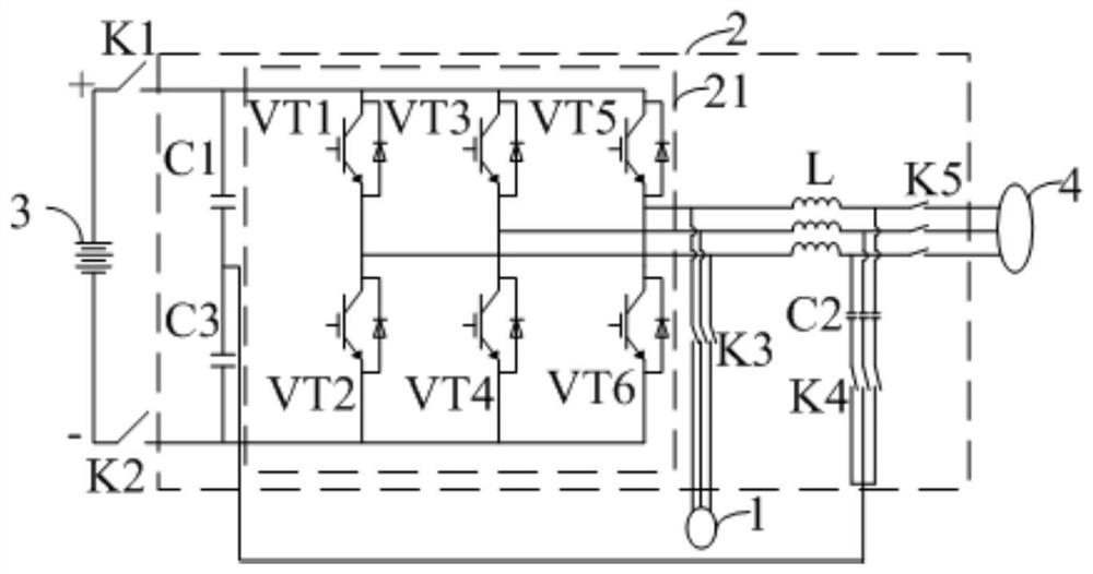
[0043] Such as figure 1 As shown, the embodiment of the present invention provides a motor control circuit, including: a motor winding 1 and a motor controller 2, the motor controller 2 includes a bidirectional inverter 21, a filter inductor module L, a filter capacitor module C2, a ...


PUM


Abstract

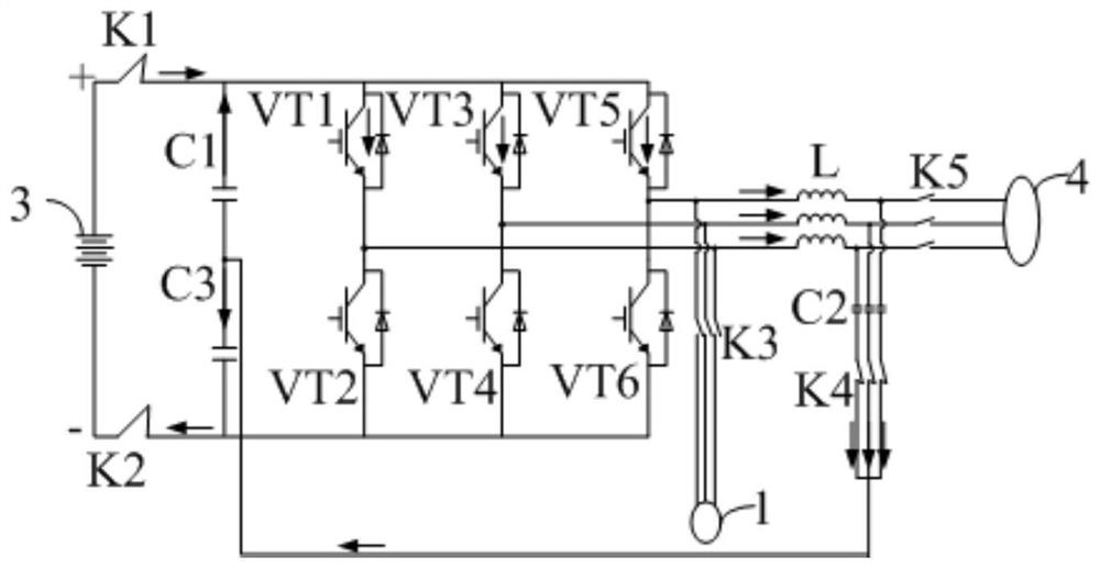
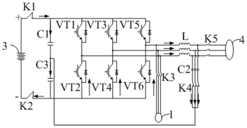
The invention discloses a motor control circuit, a vehicle and a battery self-heating control method. The battery self-heating control method comprises the following steps: receiving a battery heating command, and controlling a battery to enter a first heating mode or a second heating mode according to a judgment signal; in the first heating mode, switching off a first switch module, switching off a third switch module, and switching on a second switch module, and alternately switching on the upper bridge arm and the lower bridge arm of a bidirectional inverter; and in the second heating mode, switching off the first switch module, switching on the second switch module, the third switch module, and alternately switching on the upper bridge arm and the lower bridge arm of the bidirectional inverter. The motor control circuit provided by the invention has two battery heating modes under the cooperative action of the bidirectional inverter and each switch module, and the battery self-heating control method can efficiently heat the battery according to the temperature of the battery and the use scene of the vehicle, thereby effectively reducing the development cost of the whole vehicle, simplifying the module and reducing the development difficulty.

Description

technical field [0001] The invention generally relates to the technical field of battery heating, and in particular to a motor control circuit, a vehicle and a battery self-heating control method. Background technique [0002] Due to many problems such as resources, energy and the environment, the development of new energy has been paid more and more attention, and batteries, especially lithium batteries, as new energy carriers have become a trend, and they are more used in electric vehicles. However, new energy vehicles are limited by the low-temperature low-temperature activity of lithium batteries. In order to protect the battery, the strategy of charging with low current at low temperature is generally chosen, which makes users feel bad and limits the use of new energy vehicles. [0003] The traditional way of heating the battery mostly uses water heating scheme, which is inefficient; while the existing battery self-heating methods include: one is to use the battery self...

Claims


Application Information

Patent Timeline
Patent Type & Authority Applications(China)
IPC IPC(8): H02M7/797H02P27/06H02J7/02H02J7/00H01M10/633H01M10/63H01M10/625H01M10/615B60L58/34B60L58/10B60L53/00B60L15/20
CPCH02M7/797H02P27/06H02J7/02H02J7/0068H02J7/0069H01M10/63H01M10/633H01M10/615H01M10/625B60L15/20B60L58/34B60L58/10B60L53/00B60L2240/42B60L2240/545Y02E60/10Y02T10/64Y02T10/70Y02T10/72Y02T10/92Y02T10/7072Y02T90/14Y02T90/40
Inventor 凌和平刘海军刘俊华谭鑫武运峰
Owner BYD CO LTD
Why Eureka
Eureka Blog
Learn More