A bearing steel ball equalizing device
A bearing steel ball, equalizing technology, applied in the direction of shaft and bearing, bearing components, mechanical equipment, etc., can solve problems such as affecting assembly work, reducing performance, affecting steel ball equalizing efficiency, etc., to achieve high work efficiency, improve The effect of using performance
- Summary
- Abstract
- Description
- Claims
- Application Information
AI Technical Summary
Problems solved by technology
Method used
Image

Examples
Embodiment example 1
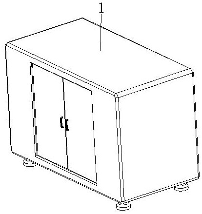
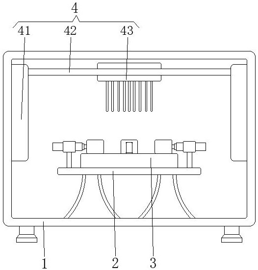
[0034] see Figure 1-8 , the present invention provides a technical solution: a bearing steel ball equalization device, including a housing 1, a workbench 2, a clamping device 3, and a ball distributing device 4. The clamping device 3 is arranged on the top of the workbench 2, and the ball distributing device 4 is arranged on the inner wall of the shell 1 and is located above the clamping device 3;
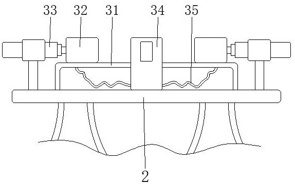
[0035] The clamping device 3 is provided with a base shell 31, an outer ring fixing device 32, a cylinder 33, an inner ring fixing device 34, and a hose 35. The bottom of the base shell 31 is fixedly connected to the top of the workbench 2, and the outer ring fixing device 32 is arranged on On both sides corresponding to the top of the base shell 31, the surface of the cylinder 33 is fixed on the top of the workbench 2, the working end of the cylinder 33 is fixedly connected to the surface side of the outer ring fixing device 32, and the inner ring fixing device 34 is arranged on ...
Embodiment example 2
[0037] The outer ring fixing device 32 is provided with a clamping block 321, a sliding pressure plate 322, and a compressed air bag 323. The bottom of the clamping block 321 is slidably connected to the top of the base shell 31, and the sliding pressure plate 322 is slidably connected to the inner side of the clamping block 321. The airbag 323 is set inside the clamping block 321 and is located at the position of the sliding platen 322. The exhaust end of the compressed airbag 323 communicates with one end of the hose 35. When the cylinder 33 is elongated, the outer ring fixing device 32 is driven as a whole to move to the bearing. , when the protruding part on the surface of the sliding pressure plate 322 is in contact with the surface of the bearing, with the continuous movement of the outer ring fixing device 32, the sliding pressure plate 322 will press the compressed air bag 323, so that the internal gas is transported through the hose 35 , and use the gas pressure to mak...
Embodiment example 3
[0039] The inner ring fixing device 34 is provided with a core tube 341, an expansion air bag 342, a conical top block 343, and an ejection fixing device 344. The surface of the core tube 341 is fixedly connected to the top of the base shell 31, and the expansion air bag 342 is arranged on the inner wall of the core tube 341. At the bottom, the inlet end of the expansion air bag 342 communicates with one end of the hose 35, the conical top block 343 is slidably connected to the inside of the core tube 341 and is located at the top of the expansion air bag 342, and the ejection fixing device 344 is arranged inside the core tube 341 And it is close to the top position and is connected with the surface top of the conical top block 343 .
[0040] The ejector fixing device 344 is provided with a jacking block device 3441, an arc-shaped elastic piece 3442, and a capsule body 3443. The jacking block device 3441 is slidably connected to the inside of the core tube 341 and is close to t...
PUM
 Abstract
Description
Claims
Application Information
 - R&D
- Intellectual Property
- Life Sciences
- Materials
- Tech Scout
- Unparalleled Data Quality
- Higher Quality Content
- 60% Fewer Hallucinations
Browse by: Latest US Patents, China's latest patents, Technical Efficacy Thesaurus, Application Domain, Technology Topic, Popular Technical Reports.
© 2025 PatSnap. All rights reserved.Legal|Privacy policy|Modern Slavery Act Transparency Statement|Sitemap|About US| Contact US: help@patsnap.com