
Optically integrated optical fiber sensing demodulation module

A sensing solution and optical technology, applied in the field of photoelectric detection, can solve the problems of many passive devices, temperature calibration error of the demodulation system, and labor-hours, etc., and achieve the goal of large quantity, reduced fiber-spinning man-hours, and long-span-fiber-spinning man-hours Effect

Pending Publication Date: 2022-02-15
NANJING MOVELASER TECH CO LTD
View PDF8 Cites 0 Cited by
  • Summary
  • Abstract
  • Description
  • Claims
  • Application Information

AI Technical Summary

Problems solved by technology

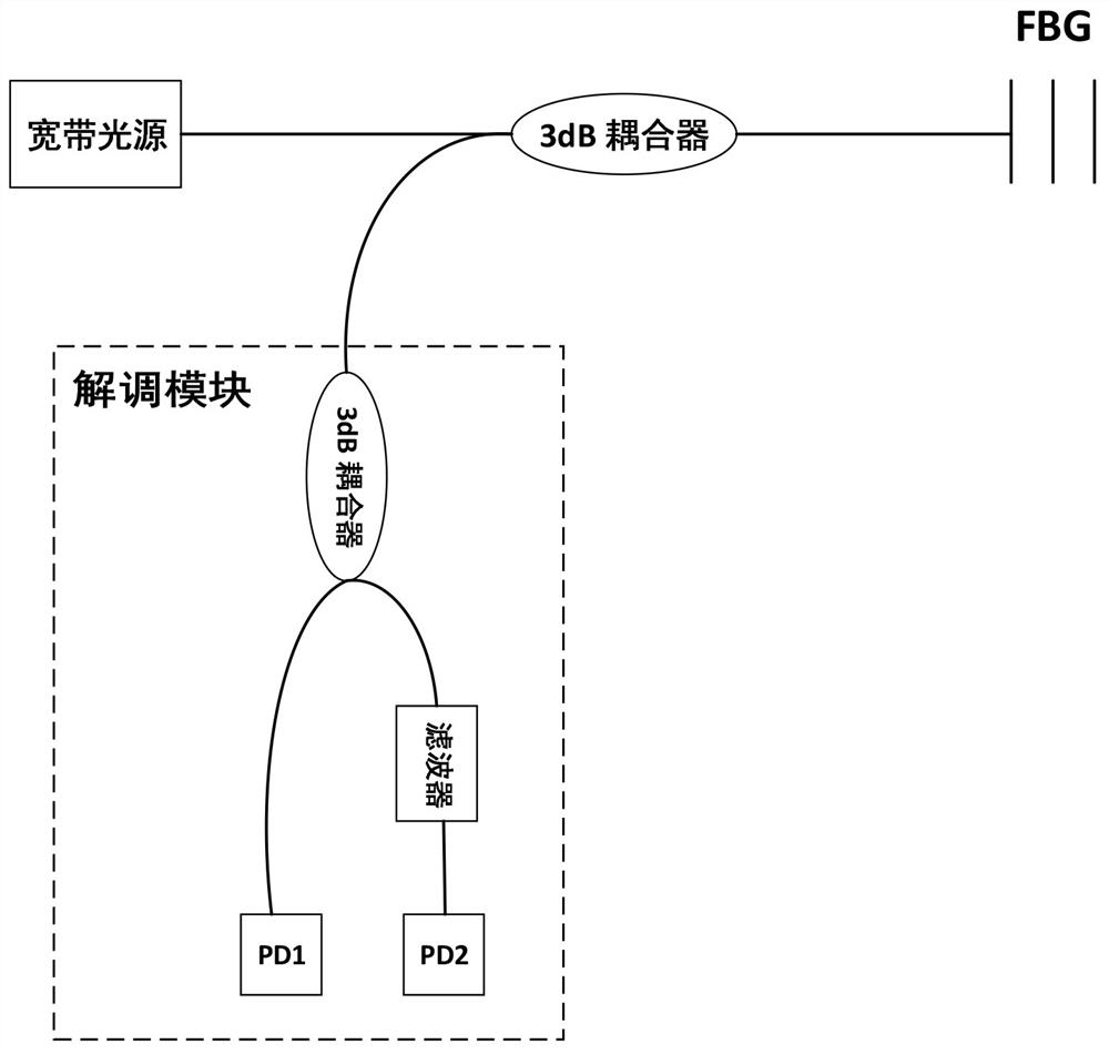
[0006] One is that multi-channel parallel detection is required in practical applications. Assuming that the number of detection channels required is N, the number of passive components required for the demodulation module reaches 4 N. Taking 9 channels as an example, the number of passive components reaches 36, and the number of optical fiber components is fused. And coiling will take a lot of man-hours, which indirectly increases the cost of the instrument;
[0007] The second is that the all-fiber device is made by collimator coupling, so it will introduce coupling loss into the demodulation module, and introduce additional systematic errors into the calibration function of the demodulation module;
[0008] The third is that the calibration function curve of the demodulation module is affected by temperature. In order to eliminate this error, it is necessary to calibrate the function curve of the demodulation module at different temperatures. Since there are many passive devices in the demodulation module, the coiled devices occupy a large volume, reaching The thermal equilibrium time is long, and the calibration time is long, which affects the production efficiency of the instrument;
[0009] Fourth, due to the large working temperature range of the demodulator, it is impossible to perform temperature calibration for each temperature operating point, so the temperature state curve in the middle of the measurement temperature point needs to be fitted by an algorithm, which will introduce temperature calibration errors to the demodulation system

Method used


Image

  • Optically integrated optical fiber sensing demodulation module
  • Optically integrated optical fiber sensing demodulation module
  • Optically integrated optical fiber sensing demodulation module

Examples


Embodiment Construction

[0032] The present invention will be further described below in conjunction with embodiment, but protection scope of the present invention is not limited to this:

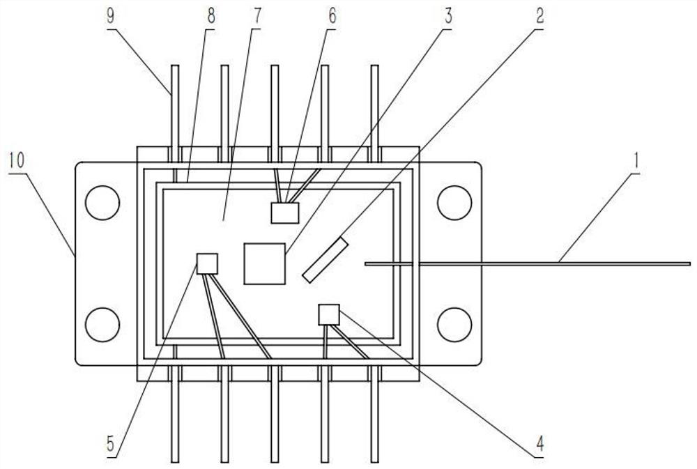
[0033] combine figure 2, the signal light to be detected is collimated and output by the fiber collimator 1, and is incident on the beam splitter 2 at an angle of 45 degrees. The beam splitter 2 is made of ultraviolet fused silica substrate. In a preferred embodiment, the size of the beam splitter 2 is 1.5 mm (length)*1.4 mm (width)*1.4 mm (height), and the wedge angle is 0.5°). The incident surface is coated with a 50:50 depolarized spectroscopic coating to eliminate polarization-related loss, and the transmission surface is coated with a depolarized anti-reflection coating. The reflected light is incident on the reference path photodetector 4 for eliminating power fluctuations, and the transmitted light is incident on the filter 3 . The incident surface of the filter 3 can be coated with the corresponding film...


PUM

PropertyMeasurementUnit
wavelengthaaaaaaaaaa
widthaaaaaaaaaa

Abstract

The invention discloses an optically integrated optical fiber sensing demodulation module. The module is characterized by comprising an optical fiber collimator, a beam splitter, a filter, a reference path photoelectric detector, a signal path photoelectric detector, an optical substrate, pins and a packaging shell, and the optical fiber collimator, the beam splitter, the filter, the reference path photoelectric detector and the signal path photoelectric detector are all mounted on the optical substrate and are packaged and protected by the packaging shell; the reference path photoelectric detector and the signal path photoelectric detector are connected with the pin and the pin leads out the packaging shell; a signal needing to be detected is collimated and input through the optical fiber collimator, and the beam splitter is arranged on the output side of the signal passing through the optical fiber collimator at an angle of 45 degrees; and the reference path photoelectric detector is arranged on the reflection side of the beam splitter, the filter is arranged on the transmission side of the beam splitter, and the signal path photoelectric detector is arranged on the transmission side of the filter. After the integrated module scheme is adopted, the module is reduced into one device , so the fiber coiling time is greatly reduced.

Description

technical field [0001] The invention belongs to the field of photoelectric detection, in particular to an optically integrated optical fiber sensing demodulation module. Background technique [0002] The fan blade load monitoring system is an important part of the fan system. The traditional monitoring method is to sense and measure the strain with electronic strain gauges, and obtain the strain value through electronic strain gauges. However, due to the poor long-term reliability of electronic strain gauges and their susceptibility to electromagnetic interference, it is impossible to reliably measure the load of fan blades for a long time. Optical fiber sensing technology is gradually applied in the field of wind power due to its strong anti-electromagnetic interference ability, stable and reliable long-term use, large measuring range, and high measurement accuracy. The optical fiber sensing system mainly includes two parts: the fiber grating sensor and the signal demodul...

Claims


Application Information

Patent Timeline
Patent Type & Authority Applications(China)
IPC IPC(8): G01D5/353
CPCG01D5/353G01D5/35338
Inventor 周军罗浩李智
Owner NANJING MOVELASER TECH CO LTD
Learn More