Double-layer hydrothermal flash evaporation device and method
A flash evaporation device and double-layer structure technology, which is applied in the field of double-layer structure hydrothermal flash evaporation device, can solve the problems of low conversion efficiency of organic matter, low flash evaporation efficiency, and poor blasting effect, etc., so as to increase conversion efficiency and The effect of generating volume, improving flash evaporation efficiency, and facilitating installation and removal of wearing parts
- Summary
- Abstract
- Description
- Claims
- Application Information
AI Technical Summary
Problems solved by technology
Method used
Image
Examples
Embodiment 1
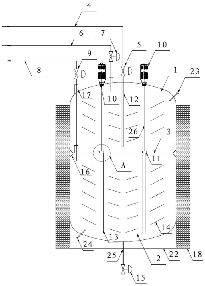
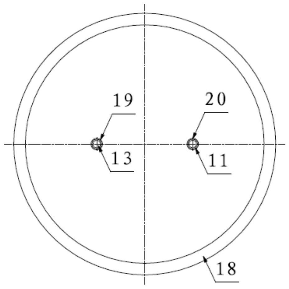
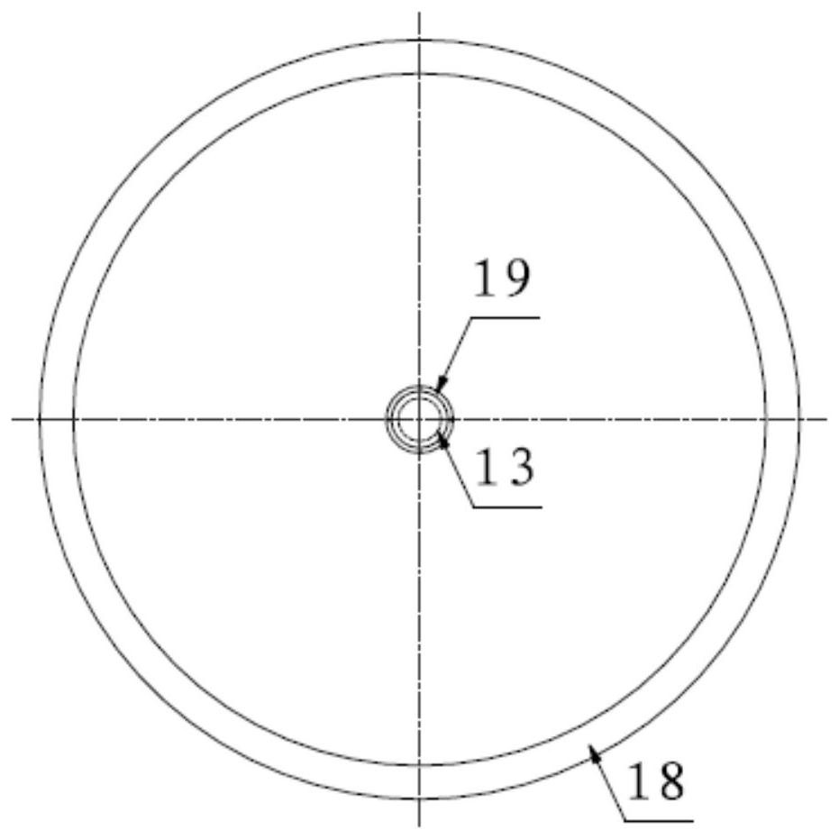
[0034] Embodiment 1 of the present application provides a double-layer structure hydrothermal flash device, such as figure 1 As shown, it includes an upper flash tank body 1, a lower flash tank body 2, a stainless steel interlayer 3, a base 22, an insulation layer 18, and the like. The double-layer structure hydrothermal flash evaporation device is generally cylindrical, and the top cover and the bottom cover are hemispherical, and are supported by the base 22 . An insulating layer 18 is provided outside the double-layer structure hydrothermal flash evaporation device to reduce heat dissipation and increase the amount of steam generated during the flash evaporation process. The stainless steel interlayer 3 is arranged between the upper flash tank body 1 and the lower flash tank body 2 for isolating materials. The wall thickness of the stainless steel interlayer 3 adopts more than 8mm, and a stainless steel interlayer support 16 is provided on the inner wall between the upper ...
Embodiment 2
[0042] Embodiment 2 of the present application provides a working method of a double-layer structure hydrothermal flash evaporation device, including the following steps:
[0043] S1. When the high-temperature and high-pressure material after hydroheating passes through the feed pipe 4 under the control of the feed control valve 5, it enters the bottom of the upper flash tank body 1 through the upper material feed guide tube 12, and is discharged in the upper flash tank. Instantaneous release of pressure in body 1 occurs the first flash. After the material enters the bottom of the upper flash tank 1, during the flashing process, through the release of pressure, the material and water vapor move along the deflector 14 to the wall of the upper flash tank 1 and circulate from the top Backflow, the high-temperature material finally accumulates on the stainless steel interlayer 3, and the water vapor rises along the inner wall of the upper flash tank 1 through the deflector 14, and...
PUM
| Property | Measurement | Unit |
|---|---|---|
| thickness | aaaaa | aaaaa |
Abstract
Description
Claims
Application Information
 - R&D
- Intellectual Property
- Life Sciences
- Materials
- Tech Scout
- Unparalleled Data Quality
- Higher Quality Content
- 60% Fewer Hallucinations
Browse by: Latest US Patents, China's latest patents, Technical Efficacy Thesaurus, Application Domain, Technology Topic, Popular Technical Reports.
© 2025 PatSnap. All rights reserved.Legal|Privacy policy|Modern Slavery Act Transparency Statement|Sitemap|About US| Contact US: help@patsnap.com


