


Quick Research
Generate reliable direction feasibility study reports for your R&D in just a few steps.

Technical Q&A
Discover and master advanced knowledge NOW. Basics, ideas, possibilities, all at once.

Find Solutions
As an expert in R&D theories, this can generate solutions to your technical problems instantly.

Evaluate Feasibility
Analyze your overall solution with one click, know your potential R&D risks in advance.

Monitor Landscape
Get weekly tech updates, stay abreast of the latest tech innovations and key insights.
Hot runner unit, injection molding system and control method of injection molding system
A control method and hot runner technology, applied in the field of plastic injection molding, can solve the problems of pressure data unable to form experience precipitation, injection pressure deviation, unable to reflect injection pressure loss, etc.
- Summary
- Abstract
- Description
- Claims
- Application Information
AI Technical Summary
Problems solved by technology
Method used
Image

Examples
Embodiment 1
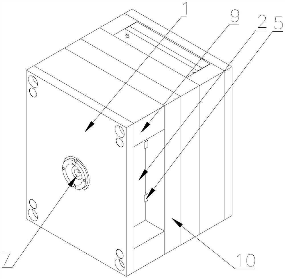
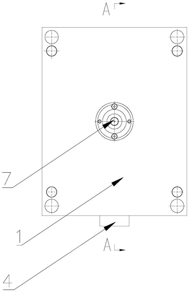
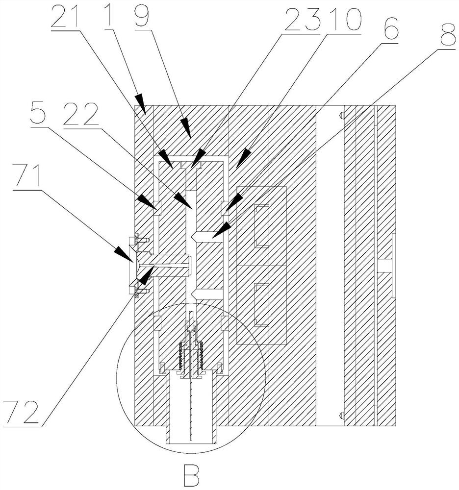
[0042] Such as Figure 1 to Figure 4As shown, a hot runner unit is provided in this embodiment, including a fixed plate 1 and a splitter plate 2, a nozzle 7 is provided on the fixed plate 1, the nozzle 7 includes a nozzle body 71, and a main flow channel 72 is arranged in the nozzle body 71. The manifold 2 includes a manifold body 21, the manifold body 21 is provided with a flow channel 22 communicating with the main channel 72, and a pressure sensor 221 is installed in the flow channel 22 for detecting the pressure of the thermal fluid in the flow channel 22, and then the flow channel 22 The internal thermal fluid pressure is compared with the injection pressure applied on the screw, and the injection pressure is adjusted so that the thermal fluid pressure inside the runner 22 meets the requirements of the injection molding process parameters of the mold, so as to avoid the injection pressure loss caused by the wear and aging of the components of the injection unit from affect...
Embodiment 2
[0054] This embodiment provides an injection molding system with the above-mentioned hot runner unit, which also includes an injection unit and a data processing unit. The injection unit includes a barrel, a screw and a screw control device. One end of the barrel is connected to the nozzle 7, The screw control device is connected with the screw; the data processing unit is respectively connected with the pressure sensor 221 and the screw control device in communication.
[0055] In this embodiment, the data processing unit receives the pressure data of the thermal fluid in the runner 22 transmitted by the pressure sensor 221, and sends a signal to the screw control device based on the acquired pressure data of the thermal fluid in the runner 22 to control the injection pressure applied to the screw or Adjust the injection speed of the screw so that the pressure of the thermal fluid in the runner 22 meets the requirements of the injection molding process parameters to ensure the...
Embodiment 3
[0060] An embodiment of the present invention provides a control method applied to the injection molding system described above, including the following steps:
[0061] Step S1, melting the plastic particles in the barrel to obtain a hot fluid;
[0062] Step S2, determining the target injection pressure P0, the target injection velocity V0 and the target thermal fluid pressure P0' in the runner 22;
[0063] Step S3, based on the target injection pressure P0 and the target injection speed V0, control the screw to push the hot fluid into the runner 22 through the main channel 72, and obtain the actual pressure P of the hot fluid in the runner 22;
[0064] Step S4, judging the actual thermal fluid pressure P and the target thermal fluid pressure P0', if P is equal to P0', the sub-runner 22 enters the pressure holding stage; if P is less than P0', adjust the injection pressure P0 to P1 and / or the injection speed V0 is V1, and the pressure P of the thermal fluid in the flow channe...
PUM
 Abstract
Description
Claims
Application Information
 - R&D Engineer
- R&D Manager
- IP Professional
- Industry Leading Data Capabilities
- Powerful AI technology
- Patent DNA Extraction
Browse by: Latest US Patents, China's latest patents, Technical Efficacy Thesaurus, Application Domain, Technology Topic, Popular Technical Reports.
© 2024 PatSnap. All rights reserved.Legal|Privacy policy|Modern Slavery Act Transparency Statement|Sitemap|About US| Contact US: help@patsnap.com