
Hydraulic press control system, and method for machining automotive interiors by hydraulic press control system

A technology for automotive interior parts and control systems, applied to presses, manufacturing tools, etc., can solve problems such as pressure position overshoot, piston rod self-heaviness, etc.

Pending Publication Date: 2018-06-19
YANGLI GRP CORP LTD
View PDF0 Cites 7 Cited by
  • Summary
  • Abstract
  • Description
  • Claims
  • Application Information

AI Technical Summary

Problems solved by technology

Overshoot is often due to the response lag of detection components (such as pressure sensors, displacement sensors), controllers (such as PLC controllers) and actuators (such as reversing valves), and there is a gap between reaching the set value and stopping oil supply. During the time interval, the hydraulic pump has excess hydraulic oil flowing out, and the excess hydraulic oil enters the main oil cylinder, which will inevitably cause pressure overshoot or position overshoot
The piston rod has a lot of weight, and it is difficult to stop immediately under the action of inertia, which is also one of the factors causing overshoot.

Method used


Image

  • Hydraulic press control system, and method for machining automotive interiors by hydraulic press control system
  • Hydraulic press control system, and method for machining automotive interiors by hydraulic press control system

Examples


Embodiment Construction

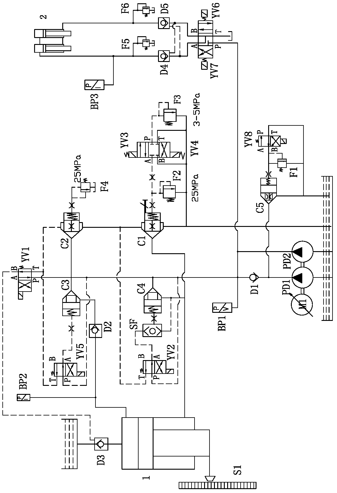
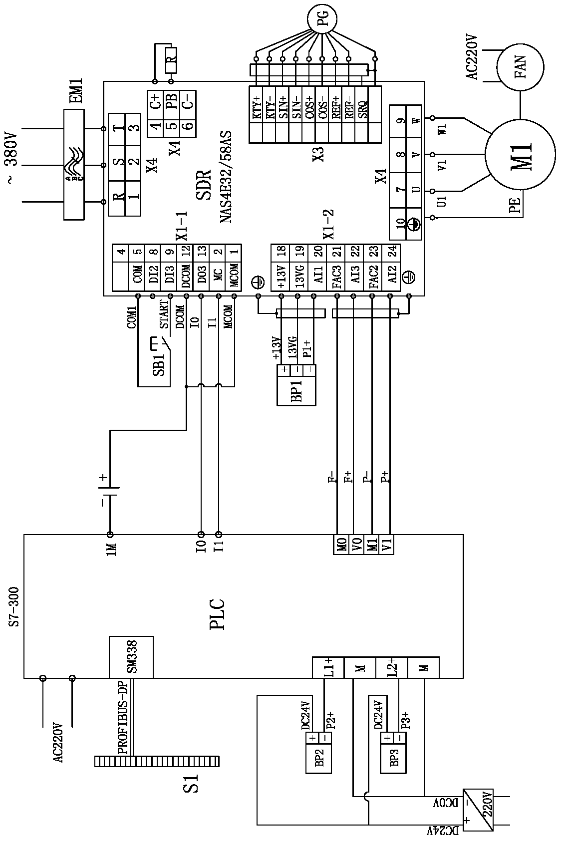
[0023] Such as figure 1 As shown, the hydraulic machine control system of the present invention includes a master cylinder 1 that drives the slider, the upper chamber of the master cylinder 1 is connected with the liquid filling tank through the hydraulic control liquid filling valve D3, and the inlet of the servo pump is connected with the main oil tank. The pump includes a low-pressure large-flow pump PD1 and a high-pressure small-flow pump PD2 driven by the same servo motor M1. The outlet of the low-pressure large-flow pump PD1 is connected to the inlet of the first one-way valve D1, and the outlet of the high-pressure small-flow pump PD2 is connected to the first one-way valve. The outlet of the one-way valve D1 is connected in parallel, the outlet of the first one-way valve D1 is connected with the inlets of the second cartridge valve C2, the third cartridge valve C3 and the fourth cartridge valve C4, the outlet of the third cartridge valve C3 is connected with the The in...


PUM


Abstract

The invention relates to a hydraulic press control system, and a method for machining automotive interiors by the hydraulic press control system. A servo pump comprises a low-pressure high-flow pump and a high-pressure low-flow pump, and an outlet of the low-pressure pump is connected to an inlet of a first check valve; an outlet of the high-pressure pump is connected to an outlet of the first check valve in parallel, and the outlet of the first check valve is connected to inlets of a second cartridge valve, a third cartridge valve and a fourth cartridge valve; the outlet of the third cartridge valve is connected to an inlet of a second check valve, and an outlet of the second check valve is connected to an upper cavity of a master cylinder; the outlet of the fourth cartridge valve is connected to a lower cavity of the master cylinder; and the lower cavity of the master cylinder is connected to the inlet of the first cartridge valve, and the outlets of the first cartridge valve and thesecond cartridge valve are connected to a main oil tank. The method for machining the automotive interiors comprises the following steps of quick descending, feeding, compression, pressure maintaining and decompression of the master cylinder, draft and slow return, ejection and return of a ramming cylinder, and back stroke of the master cylinder in sequence. The automotive interiors machined by the hydraulic press are high in yield rate and low in energy consumption.

Description

technical field [0001] The invention relates to a hydraulic machine, in particular to a control system of the hydraulic machine; the invention also relates to a method for machining interior parts of automobiles by a hydraulic machine, which belongs to the technical field of hydraulic machine tools. Background technique [0002] At present, the mainstream production process of the automobile trunk cover is as follows: take two layers of glass fiber felt, cover the front and back sides of the honeycomb paper core board, and send it to the spray booth by the manipulator to evenly spray polyurethane glue on the front and back sides, and then send it into the heating mold for heating. Forming on a hydraulic press to obtain a semi-finished car trunk. Among them, the hydraulic press is pressurized at about 18MPa once, and after 60 seconds, the hydraulic press needs to be micro-moved to exhaust once, and after about 2-3 seconds, the second pressurization is 20MPa and the pressure i...

Claims


Application Information

Patent Timeline
IPC IPC(8): B30B15/16B30B15/26B29C70/68
CPCB29C70/681B30B15/166B30B15/26
Inventor 赵雪松胡健张春祥
Owner YANGLI GRP CORP LTD
Learn More