Compression heat dissipation device

A technology of heat dissipation device and heat sink, which is applied in the direction of circuit heating device, cooling/ventilation/heating transformation, printed circuit components, etc., which can solve problems such as damage to circuit connection interface, influence on product reliability, mechanical stress damage, etc., and achieve improvement Uniformity of distribution, large safe operating temperature margin, and the effect of suppressing temperature rise

Pending Publication Date: 2022-02-08
BEIJING SATELLITE MFG FACTORY
View PDF0 Cites 1 Cited by
  • Summary
  • Abstract
  • Description
  • Claims
  • Application Information

AI Technical Summary

Problems solved by technology

As the temperature increases, the failure rate of spacecraft power products increases exponentially. Excessive temperature will endanger the junction of large-scale integrated power devices, damage the connection interface of the circuit, increase the resistance of the conductor and form mechanical stress damage. , thereby affecting the reliability of the product

Method used


Image

  • Compression heat dissipation device
  • Compression heat dissipation device

Examples


Embodiment Construction

[0020] In order to more clearly describe the embodiments of the present invention or the technical solutions in the prior art, the following will briefly introduce the drawings that are used in the embodiments. Apparently, the drawings in the following description are only some embodiments of the present invention, and those skilled in the art can also obtain other drawings according to these drawings without creative efforts.

[0021] When describing the embodiments of the present invention, the terms "vertical", "transverse", "upper", "lower", "front", "rear", "left", "right", "vertical", " The orientation or positional relationship expressed by "horizontal", "top", "bottom", "inner" and "outer" is based on the orientation or positional relationship shown in the relevant drawings, which are only for the convenience of describing the present invention and simplifying the description, and It is not to indicate or imply that the device or element referred to must have a particu...


PUM


Abstract

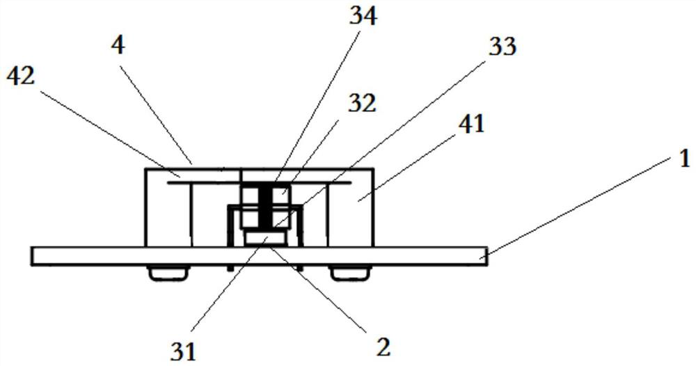
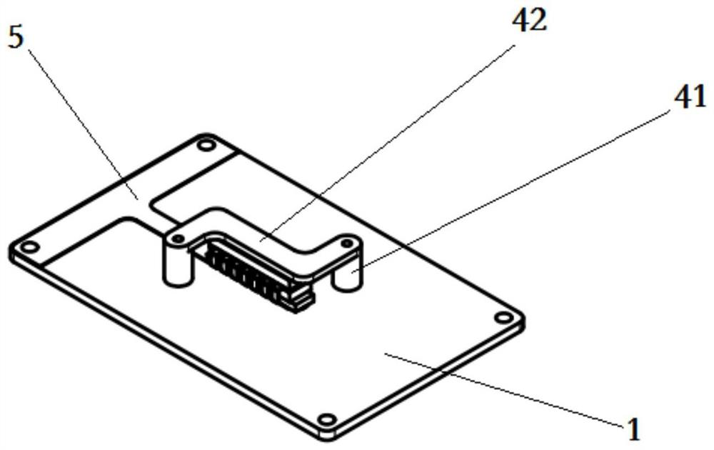
The invention relates to a compaction heat dissipation device. The device comprises a printed board, a compaction assembly, buffer pads and heat dissipation fins; the buffer pads comprise a first buffer pad and a second buffer pad; the heat dissipation fins are arranged on the printed board; the first buffer pad is arranged on a heat dissipation copper sheet; the compaction assembly and the printed board are detachably connected to the upper portions of the buffer pads; and the second buffer pad is connected with the compaction assembly. The compression heat dissipation device is characterized by further comprising a heat dissipation link, and the heat dissipation link is connected with the printed board and arranged between the heat dissipation fins and the printed board. The compression heat dissipation device can be widely applied to heat dissipation installation and uniform pressing force distribution installation of most aerospace electronic products; and a distributed installation mode can be adopted according to heat consumption and actual requirements of the devices, so that high-power heating devices can meet the uniform compression force distribution installation requirements and can bear the harsh thermal impact test environment, and the service lives of the high-power devices are prolonged.

Description

technical field [0001] The invention belongs to the field of structural components of electric equipment, and in particular relates to a compression heat dissipation device. Background technique [0002] In recent years, aerospace power supply products have developed rapidly and in-depth towards high power and intelligent components. The more extensive, this makes the thermal density of components, printed circuit boards and power supply products continue to increase, and the thermal problems of ultra-high-power components and large-scale integrated circuits have increasingly become key issues in the reliability design of power supply products. As an important item in product reliability design, thermal design has always been the focus of attention, especially for spacecraft power products. As the temperature increases, the failure rate of spacecraft power products increases exponentially. Excessive temperature will endanger the junction of large-scale integrated power devi...

Claims


Application Information

Patent Timeline
Patent Type & Authority Applications(China)
IPC IPC(8): H05K7/20H05K1/02
CPCH05K7/205H05K1/0209
Inventor 宋伟李海津刘志钢张宇许志尧顾毅裴行政杨硕谭真曾庆晨赵闯刘密王力孟晓脉吴建超穆城
Owner BEIJING SATELLITE MFG FACTORY
Why Eureka
Try Eureka