Rotary detachable steel frame and laminated slab connecting structure

A technology for connecting structures and laminated boards, which is applied to floors, building components, building structures, etc., can solve the problems of increased construction measures cost, low construction efficiency, inconvenient disassembly and reuse of temporary supports, etc. Easy to install, suitable for widespread promotion and application

Active Publication Date: 2022-02-01
CHONGQING UNIV
View PDF5 Cites 0 Cited by
  • Summary
  • Abstract
  • Description
  • Claims
  • Application Information

AI Technical Summary

Problems solved by technology

[0004] In view of this, in order to solve the problem that the temporary support installed at the bottom of the existing precast concrete composite slab is not easy to disassemble and reuse, resulting in increased cost of construction measures and low construction efficiency problem, providing a connection structure between a rotating detachable steel frame and a laminated plate

Method used


Image

  • Rotary detachable steel frame and laminated slab connecting structure
  • Rotary detachable steel frame and laminated slab connecting structure
  • Rotary detachable steel frame and laminated slab connecting structure

Examples


Embodiment 1

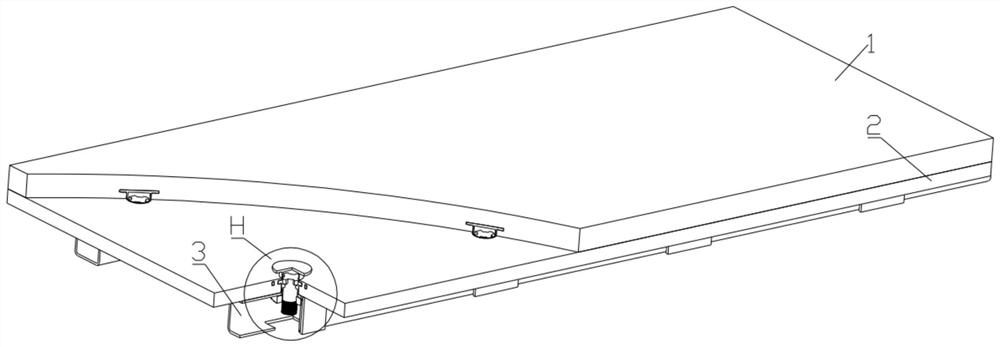
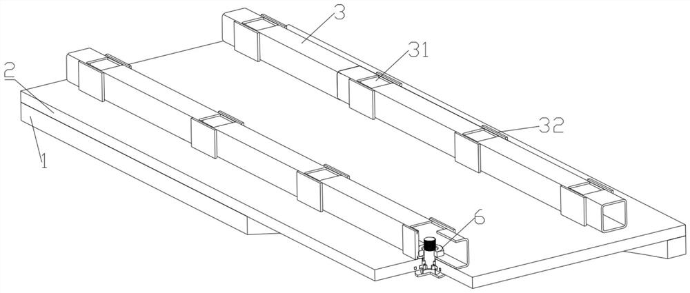
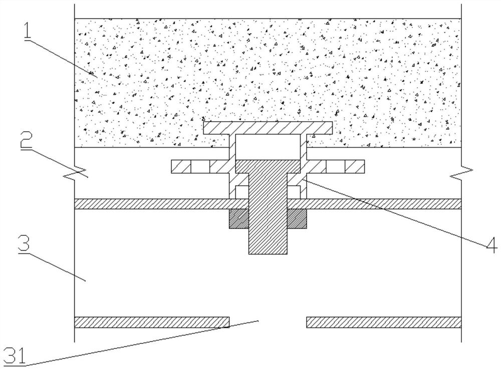
[0064] Such as Figure 1~4 as well as Figure 37 The connection structure between the rotating detachable steel frame and the laminated slab shown includes a prefabricated bottom slab 2, a cast-in-place concrete layer 1 poured on the prefabricated bottom slab 2, and a number of square steel pipes 3 detachably fixed on the prefabricated bottom slab 2 for support. ; The square steel pipes 3 are longitudinally arranged along the prefabricated floor 2 and arranged side by side. A square hole 31 is provided on the side of the square steel pipe 3 away from the prefabricated bottom plate 2, a steel pipe hole 33 is provided on the square steel pipe 3 on the side opposite to the square hole 31, and a bottom plate hole through which both sides are connected is provided on the prefabricated bottom plate 2 corresponding to the steel pipe hole 33. 21; the steel pipe hole 33 and the corresponding bottom plate hole 21 are installed with a large Π-shaped embedded part 4, a T-shaped connector...

Embodiment 2

[0069] Such as Figure 13 , 16 The structural schematic diagram of the embedded part shown in ~ 18, the difference between the second embodiment and the first embodiment is that the embedded part 4 includes a cylindrical embedded part body 45, a round body integrally formed and installed on the top of the embedded part body 45 Shaped bottom plate 41 and 8 steel bars 47 that are evenly welded in the middle part of the embedded part cylinder body 45 . The design of the steel bar 47 enhances the connection stability between the embedded part 4 and the prefabricated bottom plate 2 , and facilitates the bonding of the prefabricated bottom plate 2 and the embedded part 4 .

Embodiment 3

[0071] Such as Figure 19-20 , 23-24 and 26-27 show the structural schematic diagrams of the embedded parts. The difference between the third embodiment and the first embodiment is that the embedded part 4 includes a cylindrical embedded part body 45, which is set on the embedded part body. The hoisting hole 46 at the top of 45 and the annular plate 43 integrally formed on the middle part of the pre-embedded body 45 . Eight fan-shaped locking teeth I 44 are uniformly formed on the inner wall of the embedded part cylinder body 45, and the central angle of the locking teeth I 44 is 22.5°. Eight through-holes 42 are evenly opened on the annular plate 43. When the prefabricated bottom plate 2 is prefabricated, part of the slurry flows through the through-holes 42, which facilitates the bonding of the prefabricated bottom plate 2 and the embedded parts 4, and improves the installation stability of the embedded parts 4. . At the same time, the design of the annular plate 43 also e...


PUM


Abstract

The invention belongs to the field of building components, and relates to a rotary detachable steel frame and laminated slab connecting structure which comprises a prefabricated bottom plate, a cast-in-place concrete layer poured on the prefabricated bottom plate and a plurality of square steel pipes detachably fixed to the prefabricated bottom plate and playing a supporting role. Square holes are formed in the sides, away from the prefabricated bottom plates, of the square steel pipes, steel pipe holes are formed in the sides, facing the square holes, of the square steel pipes, and bottom plate holes with the two sides communicated are formed in the prefabricated bottom plates corresponding to the steel pipe holes. Large n-shaped embedded parts, T-shaped connecting pieces matched with the embedded parts for use and nuts used for fixing the connecting pieces are mounted in the steel pipe holes and the corresponding bottom plate holes; and the problems that the construction measure cost is increased and the construction efficiency is low due to the fact that a temporary support installed at the bottom of an existing prefabricated concrete laminated slab is inconvenient to disassemble and reuse are solved.

Description

technical field [0001] The invention belongs to the field of building components and relates to a connection structure between a rotating detachable steel frame and a laminated plate. Background technique [0002] Concrete composite slab is an assembled integral structure composed of prefabricated prestressed concrete floor (or called prefabricated floor) and cast-in-place concrete layer (or called cast-in-place slab), which has good integrity and earthquake resistance. The concrete laminated slab saves the formwork in the construction, speeds up the construction progress, and thus reduces the engineering cost. At present, the technological process of making concrete laminated slabs at the construction site is as follows: laying a prefabricated floor on the construction site, pouring concrete on the prefabricated floor, and forming a cast-in-place slab after the cast-in-place concrete solidifies, forming a precast concrete laminated slab. [0003] Due to the heavy weight of...

Claims


Application Information

Patent Timeline
Patent Type & Authority Applications(China)
IPC IPC(8): E04B5/17E04B1/38E04B1/41
CPCE04B5/17E04B1/38E04B1/41E04B2005/176
Inventor 白久林梁天龙金双双杨经纬杨大伟
Owner CHONGQING UNIV
Why Eureka
Try Eureka