Oil pipe and sucker rod turnover system and method
A turnover system and sucker rod technology, applied in the direction of drill pipe, drill pipe, casing, etc., can solve the problems of pipe and rod data information unification, information data transmission without consistency and operability, and data information disconnection, etc. Achieve the effect of sufficient technical preparation, solving the problem of repetitive labor, and single action
- Summary
- Abstract
- Description
- Claims
- Application Information
AI Technical Summary
Problems solved by technology
Method used
Image

Examples
Embodiment 1
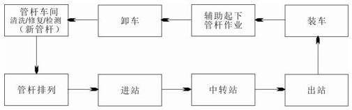
[0057] see Figure 1-Figure 9 , a turnover system for oil pipes and sucker rods, comprising a pipe arrangement unit, a transfer station storage unit, an inbound and outbound conveyance unit, and a loading conveyance unit.
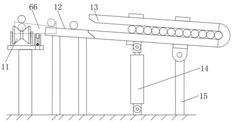
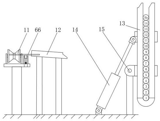
[0058] Wherein, the pipe arrangement unit includes a roller table, and one side of the roller table 11 is provided with an inclined material rack 12, and one side of the material rack 12 is provided with a displacement pipe arrangement device 13 for vertically placing the pipe rods, and the displacement pipe arrangement device 13 The bottom is rotatably connected with the upper end of the support through a rotating shaft 15. The bottom of the displacement pipe rower 13 is provided with a displacement cylinder 14 for driving the displacement pipe rower 13 to rotate. The displacement pipe rower 13 is a U-shaped structure, and the displacement row The opening end of the tube 13 is movably connected with one end of the material rack 12 .
[0059] Pipe rod arra...
Embodiment 2
[0074] Basically the same as embodiment 1, the difference is: as Figure 9 and Figure 10 As shown, the work assistance vehicle includes a vehicle chassis 71, and also includes a fixing unit, a turning and rolling unit and a driving unit.
[0075] Wherein, the fixing unit is a plurality of faceplate supports 59 provided on the vehicle chassis 71, such as Figure 12 As shown, a plurality of universal balls 60 are installed on the inner circular track of the faceplate support 59; the rotary rolling unit includes a faceplate 56 which is rotatably arranged in the faceplate support 59, and adjacent faceplates 56 are connected by connecting plates 58, and inside the faceplate 56 There are a plurality of pipe rod grooves 57 radially in the center, and the depths of the pipe rod grooves 57 are different, so that under the premise of ensuring the strength, there are as many pipe rod grooves 57 as possible. The width of the pipe rod groove 57 is slightly larger than the diameter of th...
Embodiment 3
[0092] Basically the same as Embodiment 1, the difference is that the vehicle chassis 71 is also provided with an oil dirt collection system, such as Figure 12 As shown, the oil pollution collection system includes a baffle plate 68 arranged on the edge of the vehicle chassis 71, the vehicle chassis 71 is provided with a liquid accumulation tank 70 for storing oil, and the vehicle chassis 71 is provided with a floor drain hole 69 communicating with the liquid accumulation groove 70 . The oil dirt carried by the pipe rod is collected on the vehicle chassis 71, and is blocked by the baffle plate 68 and cannot flow to the ground. The oil on the vehicle chassis 71 flows into the liquid accumulation tank 70 through the floor drain hole 69, and the liquid accumulation tank 70 is emptied after returning to the factory. The oil pollution collection system of the operation auxiliary vehicle replaces the anti-seepage cloth or boat-shaped oil pan of the traditional ground pipe rack.
...
PUM
 Abstract
Description
Claims
Application Information
 - R&D
- Intellectual Property
- Life Sciences
- Materials
- Tech Scout
- Unparalleled Data Quality
- Higher Quality Content
- 60% Fewer Hallucinations
Browse by: Latest US Patents, China's latest patents, Technical Efficacy Thesaurus, Application Domain, Technology Topic, Popular Technical Reports.
© 2025 PatSnap. All rights reserved.Legal|Privacy policy|Modern Slavery Act Transparency Statement|Sitemap|About US| Contact US: help@patsnap.com