


Quick Research
Generate reliable direction feasibility study reports for your R&D in just a few steps.

Technical Q&A
Discover and master advanced knowledge NOW. Basics, ideas, possibilities, all at once.

Find Solutions
As an expert in R&D theories, this can generate solutions to your technical problems instantly.

Evaluate Feasibility
Analyze your overall solution with one click, know your potential R&D risks in advance.

Monitor Landscape
Get weekly tech updates, stay abreast of the latest tech innovations and key insights.
Electroplating heating device
A heating device and heating box technology, which is applied in plating baths, electrolysis components, electrolysis processes, etc., can solve the problems of slow heating speed and uneven heating of electroplating solution, and achieve the effects of uniform heating, stable decline and high efficiency.
- Summary
- Abstract
- Description
- Claims
- Application Information
AI Technical Summary
Problems solved by technology
Method used
Image

Examples
Embodiment 1
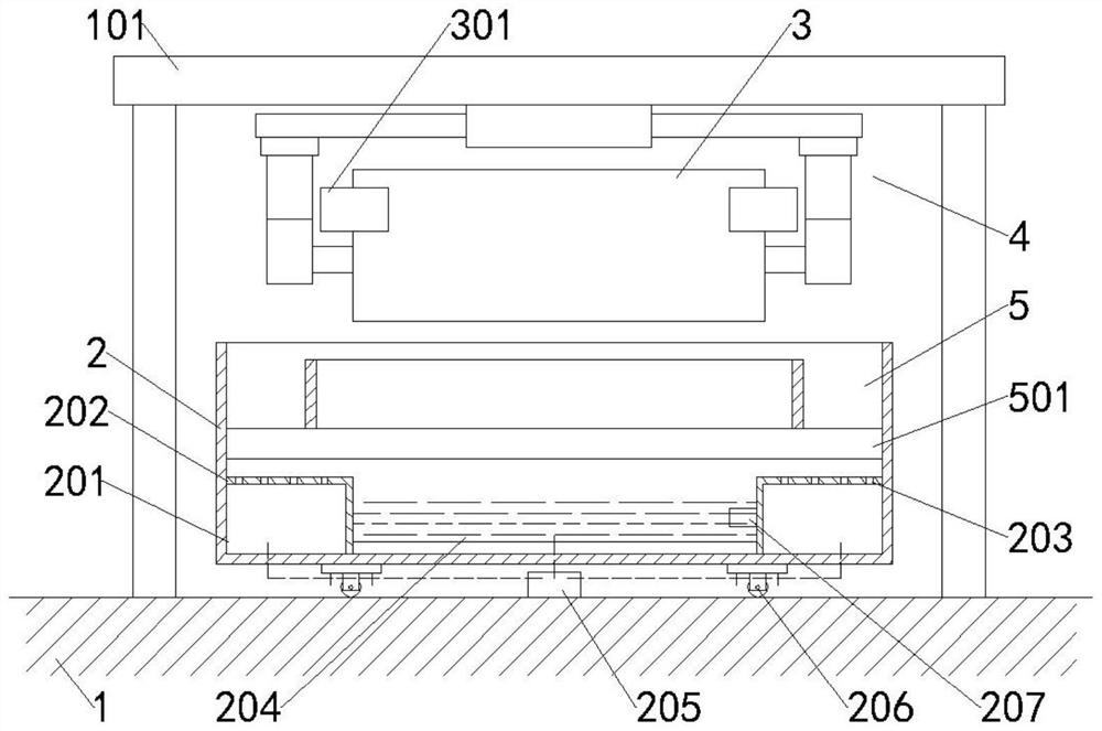
[0032] Such as Figure 1-Figure 7 As shown, a kind of electroplating heating device comprises heating box 2, and universal wheel 206 is installed on its bottom end, is convenient to the movement of heating box 2, and heating box 2 is positioned on foundation 1, is filled with in heating box 2 and is used for electroplating box 3 The heating medium 204 of heating, and heating medium 204 is water, and heating medium 204 is positioned at electroplating box 3 outsides, guarantees that the electrolytic solution in electroplating box 3 can not cause pollution; Electroplating box 3 is equipped with cross support 302, and cross support 302 central position is installed There is a motor two 303, and a stirring shaft 304 is installed at the bottom of the motor two 303, which is used to stir the electroplating solution in the electroplating box 3 to ensure that the electroplating solution is heated evenly. Stir to ensure that the electroplating solution in the electroplating box 3 is hea...
Embodiment 2
[0038] Such as figure 1 with Figure 4 As shown, a hydraulic cylinder 510 is installed in the groove 508, and a support block 509 for fixing the electroplating box 3 is installed on one end of the hydraulic cylinder 510. During the heating process of the electroplating box 3, it is fixed by the support block 509 to ensure that the electroplating box 3 Evenly heated everywhere, when the electroplating box 3 moves down, the support block 509 is located in the groove 508, and when the electroplating box 3 moves down to the limit position, the hydraulic cylinder 510 pushes the support block 509 to fix the electroplating box 3.
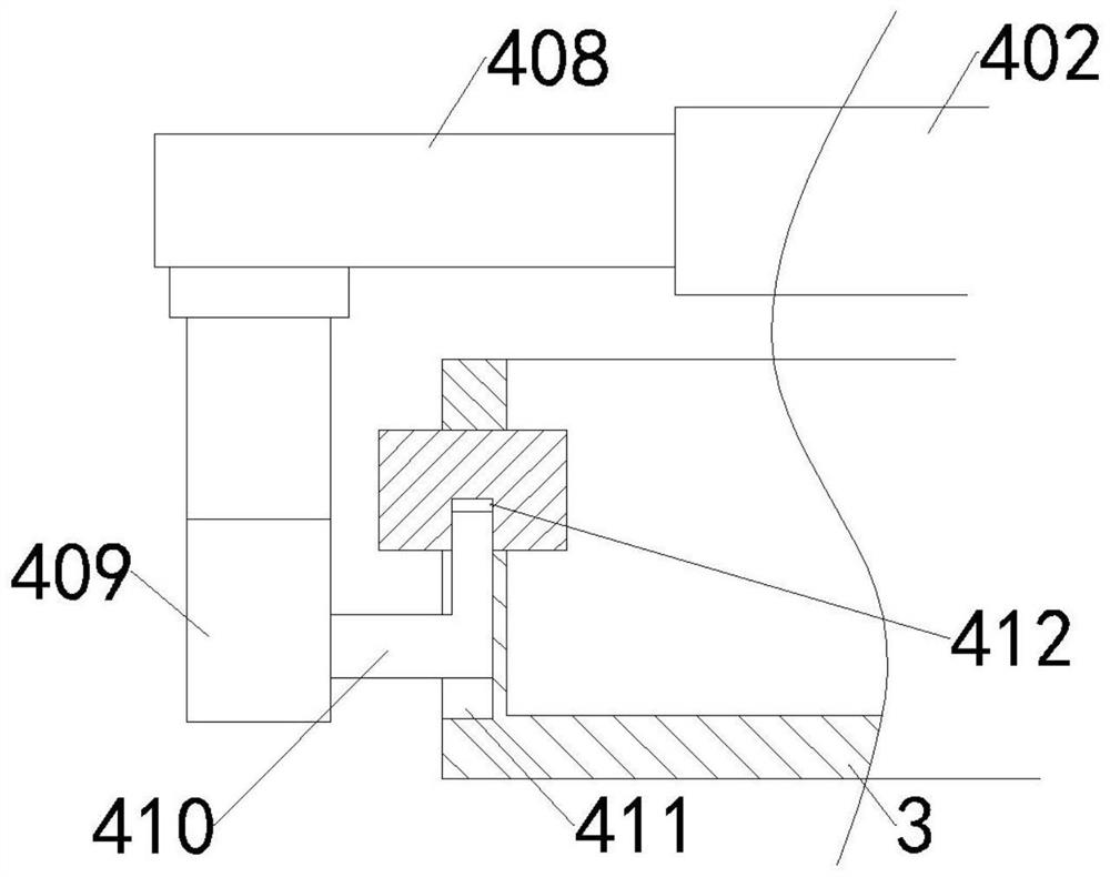
[0039] Boss 301 is fixedly installed on electroplating box 3, and boss 301 is used to limit the extreme position that electroplating box 3 moves down, and electroplating box 3 two sides are provided with positioning groove 411, and boss 301 is provided with limit groove 412, and limit groove 412 communicates with the positioning groove 411.
[0040] In o...
Embodiment 3
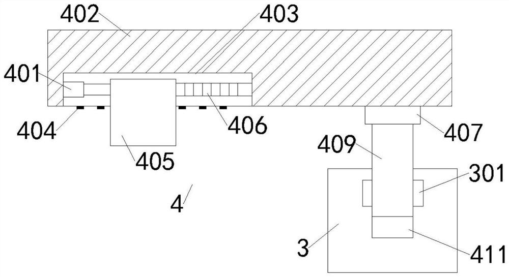
[0042] Such as Figure 1-Figure 3 As shown, the supporting mechanism 4 includes a turntable 402, a gravity block 405 and a telescopic cylinder 2 409 that controls the lifting of the electroplating box 3. The turntable 402 is movably installed on the support 101, and one end of the turntable 402 is symmetrically equipped with an extension plate 408, and the bottom end of the extension plate 408 is installed Telescopic cylinder two 409 is arranged, and rotating disk 407 is installed between telescopic cylinder two 409 and extension plate 408, and telescopic cylinder two 409 sides are fixedly installed with support rod 410, and when support mechanism 4 works, support rod 410 is positioned at limit groove 412 and positioning Inside the groove 411.
[0043] In order to ensure the stability of the supporting mechanism 4, the other end of the turntable 402 is provided with a balance groove 403, and a gravity block 405 is movable installed in the balance groove 403, and one side of th...
PUM
 Abstract
Description
Claims
Application Information
 - R&D Engineer
- R&D Manager
- IP Professional
- Industry Leading Data Capabilities
- Powerful AI technology
- Patent DNA Extraction
Browse by: Latest US Patents, China's latest patents, Technical Efficacy Thesaurus, Application Domain, Technology Topic, Popular Technical Reports.
© 2024 PatSnap. All rights reserved.Legal|Privacy policy|Modern Slavery Act Transparency Statement|Sitemap|About US| Contact US: help@patsnap.com