
Continuous production forming equipment for zipper teeth

A technology of forming equipment and zipper teeth, applied in the field of zippers, can solve the problems of inapplicability to the production needs of small and medium-sized enterprises, high loss, short service life of cutting tools, etc., so as to improve the quality of zipper products, improve the service life, and ensure continuous operation. Effect

Pending Publication Date: 2022-01-28
广州兴会拉链有限公司
View PDF5 Cites 1 Cited by
  • Summary
  • Abstract
  • Description
  • Claims
  • Application Information

AI Technical Summary

Problems solved by technology

In the Y wire method, the metal wire with a basically Y-shaped section is cut into a predetermined thickness, and then pressed on the zipper tape one by one. The surface of the chain teeth produced in this way is smooth and beautiful in appearance. The production equipment required by the wire method is too large, and the production cost is also high, which is not suitable for the production needs of small and medium-sized enterprises; while in the pressurized method, the flat wire is cut by pressing the knife, and the punched out At the same time, the chain teeth are pressed on the zipper tape one by one, and the pressure method is used to produce the zipper teeth. The produced chain teeth are smooth and durable, and the production equipment required is low in cost and occupies a small area; therefore, the pressure method is widely used For the production of zipper teeth
[0003] However, the existing zipper element production equipment still has many problems when cutting and producing zipper elements: First, in order to facilitate the merging and clamping of the teeth legs of the zipper element on the cloth tape, usually the tooth head of the zipper element There is a concave part at the joint with the tooth leg. When the traditional zipper element production equipment punches the chain element with the concave part, it is easy to cause the chain element to be stuck on the cutting edge of the knife after cutting, and the automatic demoulding cannot be realized, which affects the continuity of the zipper element. production; secondly, in order to make the zipper teeth obtain greater bite force on the cloth tape, protrusions will be provided on the inner side of the two teeth legs of the zipper teeth. When the chain teeth are typesetting on the dental floss, a large gap is reserved between two chain teeth, and it is formed by multiple punching such as trimming, trimming, and cutting. The dental floss has many consumables and high production costs; finally, The punching surface of the traditional cutting tool wears out as the number of punching increases. In order to ensure the cutting accuracy of the zipper teeth, it is necessary to replace the cutting tool regularly on the punching machine. The cutting tool has a short service life, high loss and poor economic benefits.

Method used


Image

  • Continuous production forming equipment for zipper teeth
  • Continuous production forming equipment for zipper teeth
  • Continuous production forming equipment for zipper teeth

Examples


Embodiment 1

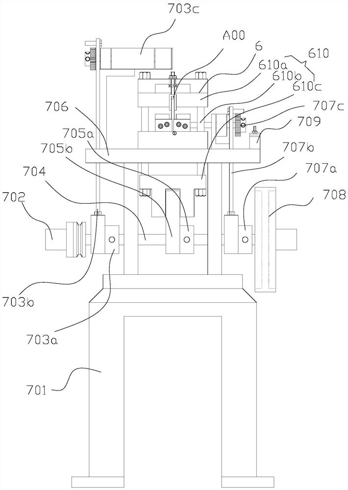
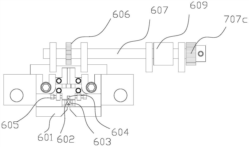
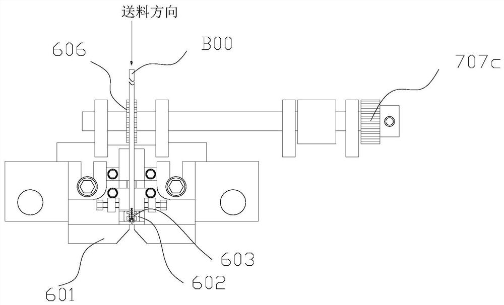
[0077] Such as Figure 1-Figure 10 and Figure 14 , Figure 15 As shown, a zipper element continuous production molding equipment is used for punching and forming the zipper element B01 from the floss B00 and pressing it on the cloth tape, including a frame 701 and a processing platform 706 set on the frame 701 , stamping device 6 and conveying structure,

[0078] The processing platform 706 is located on the upper part of the frame 701, and is fixedly connected with the frame 701, and the punching device 6 is arranged on the processing platform 706;

[0079] The stamping device 6 includes an upper die, a lower die 602, a convergent hammer 601 and a punch / die punch 604,

[0080] The upper mold includes a tool holder 608 and a cutting tool arranged from top to bottom, and the cutting tool includes a tool body A00 in a linear profile, and the upper end of the tool body A00 is provided with a The fixed clamping part 1 is provided with a punching surface 2 at the lower end, an...

Embodiment 2

[0125] One of the embodiments of the present invention, such as Figure 1-Figure 4 and Figure 11-Figure 15 As shown, the main technical solutions of this embodiment and Embodiment 1, the features that are not explained in this embodiment, use the explanation in Embodiment 1, and will not be repeated here. The difference between this embodiment and embodiment 1 is:

[0126] The cutting tool is a combination tool, including a left tool unit 11, a right tool unit 12 and an alloy sheet 14. The left tool unit 11 is fixedly connected to the right tool unit 12, and combined to form the tool body A00. The bottom of the cutter body A00 is provided with an alloy sheet 14, the alloy sheet 14 is fastened and connected with the cutter body A00, and the lower end surface of the alloy sheet 14 forms the punching surface 2; the thickness of the alloy sheet 14 is 1 mm to 3 mm; in this embodiment, the thickness of the alloy sheet 14 is preferably 1.5 mm;

[0127] It should be noted that the p...


PUM

PropertyMeasurementUnit
thicknessaaaaaaaaaa
lengthaaaaaaaaaa

Abstract

The invention discloses zipper tooth continuous production forming equipment, and belongs to the technical field of zippers, the zipper tooth continuous production forming equipment comprises a rack, a machining platform, a stamping device and a conveying structure, an upper die of the stamping device comprises a tool holder and a cutting tool which are arranged from top to bottom, the cutting tool is a linear profile, and a punching face is arranged at the lower end of the cutting tool; the punching surface is provided with an arc-shaped knife edge and a tooth-shaped knife edge which is in bilateral symmetry; a concave cavity is formed in the side, close to the arc-shaped knife edge, of the knife body, and the notch area of the cross section of the concave cavity in the extending direction of the wire profile is larger than the area of the arc-shaped knife edge; a single main shaft is arranged to be connected with a motor, power is synchronously provided for the blanking movement of a towing wheel, a feeding wheel and an upper die, the simultaneous operation of cloth tape leading-in / leading-out, dental floss conveying and zipper tooth blanking forming is achieved, and the continuous machining forming of zipper teeth is guaranteed. The concave cavity is formed in the side, close to the arc-shaped cutting edge, of the cutting tool, zipper teeth are prevented from being clamped on the cutting edge of a blanking tool, and automatic demolding is achieved.

Description

technical field [0001] The invention belongs to the technical field of zippers, and in particular relates to continuous production and molding equipment for zipper teeth. Background technique [0002] Metal zippers are widely used in garment processing, luggage production and other fields. As the core part of metal zipper, the production of chain teeth and the quality of finished products directly determine the side tensile strength of metal zipper. At present, the production forms of zipper teeth are mainly divided into Y wire method and pressure method. In the Y wire method, the metal wire with a basically Y-shaped section is cut into a predetermined thickness, and then pressed on the zipper tape one by one. The surface of the chain teeth produced in this way is smooth and beautiful in appearance. The production equipment required by the wire method is too large, and the production cost is also high, which is not suitable for the production needs of small and medium-size...

Claims


Application Information

Patent Timeline
Patent Type & Authority Applications(China)
IPC IPC(8): B21D53/50B21D28/02B21D28/14B21D43/08
CPCB21D53/50B21D28/02B21D28/14B21D43/08
Inventor 陈飞
Owner 广州兴会拉链有限公司
Learn More