
High-pressure-resistant optical fiber cabin-penetrating connector sealed by combined glue and sealing method

A technology of high-voltage resistance and connectors, which is applied in the direction of instruments, optics, light guides, etc., can solve the problems of poor adhesion, low sealing performance, and poor high-temperature resistance, so as to improve high-pressure resistance sealing performance, improve sealing strength, and improve durability. Effects of high pressure sealing performance and high temperature resistance performance

Active Publication Date: 2022-01-21
长沙军民先进技术研究有限公司
View PDF7 Cites 0 Cited by
  • Summary
  • Abstract
  • Description
  • Claims
  • Application Information

AI Technical Summary

Problems solved by technology

[0003] In the field of deep-sea optical fiber sensing and detection, sometimes it is necessary to transmit the optical signal of the optical fiber hydrophone to the inside of the sealed cabin. The optical fiber as the signal carrier needs to be sealed through the cabin. The commonly used sealing method for the cabin is to bond and seal the optical fiber and epoxy resin. The commonly used material for optical fiber coating is acrylic resin, which has poor adhesion to epoxy resin. Therefore, this method has low sealing performance against high pressure and poor high temperature resistance.

Method used


Image

  • High-pressure-resistant optical fiber cabin-penetrating connector sealed by combined glue and sealing method
  • High-pressure-resistant optical fiber cabin-penetrating connector sealed by combined glue and sealing method
  • High-pressure-resistant optical fiber cabin-penetrating connector sealed by combined glue and sealing method

Examples


Embodiment Construction

[0027] In order to enable those skilled in the art to better understand the technical solutions of the present invention, the present invention will be further described in detail below in conjunction with the accompanying drawings.

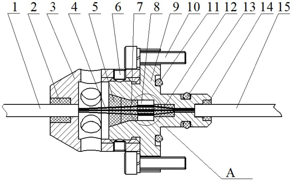
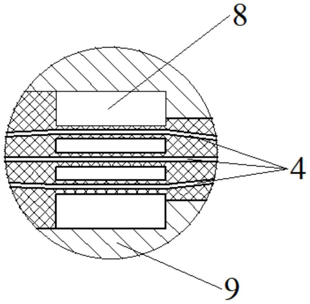
[0028] Such as figure 1 , figure 2 As shown, a combination glue-sealed high-voltage optical fiber cabin penetration connector includes an optical fiber sheath, an optical fiber protective cover 3, a fiber splitter 8 and a sealing flange seat 9, and the sealing flange seat 9 is sealed with the external sealing cabin It is fixedly connected, and the sealing flange seat 9 is provided with a first sheath connecting hole 14 at one end of the outer sealing cabin, and the end of the sealing flange seat 9 away from the outer sealing cabin is provided with a potting hole, and the potting hole includes from left to right The first potting hole 5, the second potting hole 7 and the third potting hole 12 connected in sequence, the first potting hole 5 is a ...


PUM

PropertyMeasurementUnit
viscosityaaaaaaaaaa

Abstract

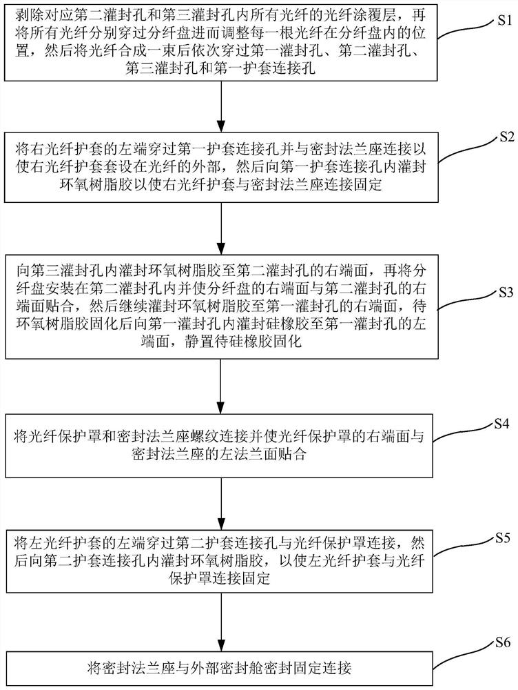
The invention specifically discloses a high-pressure-resistant optical fiber cabin-penetrating connector sealed by combined glue and a sealing method. The connector comprises an optical fiber sheath, an optical fiber protection cover, a fiber distribution disc and a sealing flange seat. The sealing flange seat is provided with a first potting hole for potting silicone rubber, and a second potting hole and a third potting hole for potting epoxy resin glue; and an optical fiber coating layer of the optical fiber at the sealing positions of the second potting hole and the third potting hole is stripped, so that the internal coating layer of the optical fiber is directly bonded with the potting epoxy resin glue. According to the invention, a silicone rubber and epoxy resin adhesive combined sealing mode is adopted, the coating layer at the sealing positions of the optical fiber corresponding to the second potting hole and the third potting hole is stripped, so that the cladding in the optical fiber is directly bonded with the epoxy resin adhesive, and the silicone rubber is directly bonded with the coating layer at the first potting hole; and the high-pressure-resistant sealing performance and the high-temperature-resistant performance of the sealing structure are effectively improved.

Description

technical field [0001] The invention relates to the technical field of optical fiber sensing engineering, in particular to a combination glue-sealed high-voltage resistant optical fiber cabin penetration connector and a sealing method. Background technique [0002] Optical fiber hydrophone is a new type of underwater acoustic sensor with optical fiber as the sensing and transmission medium. It detects underwater sound field information based on the principle of optical coherent detection. It introduces advanced photoelectric detection mechanism and optical fiber communication mechanism into underwater acoustic detection technology. After years of technical research and application verification, it has demonstrated the excellent detection performance and long transmission distance of underwater acoustic signals, large array scale, high reliability, and environmental protection. Good adaptability and other advantages are an important direction for the development of a new gene...

Claims


Application Information

Patent Timeline
Patent Type & Authority Applications(China)
IPC IPC(8): G02B6/38G01H9/00
CPCG02B6/3849G01H9/004Y02E30/30
Inventor 胥晓黄德翼柳祚前梁迅甘地王琴冯蕾杨子军唐宇
Owner 长沙军民先进技术研究有限公司
Learn More