
Dual-power hydraulic anchor rod drill carriage

A rock bolter and dual-power technology, which is applied in the direction of motor vehicles, bolt installation, electric vehicles, etc., can solve problems that do not conform to the development concept of green and low-carbon technology, high harmful gas emissions, and poor operating safety. The effect of working range, reducing labor intensity and convenient maintenance

Pending Publication Date: 2022-01-21
LANG FANG JING LONG GRAND IND MACHINERY CO LTD
View PDF0 Cites 0 Cited by
  • Summary
  • Abstract
  • Description
  • Claims
  • Application Information

AI Technical Summary

Problems solved by technology

[0002] At present, most of the roadway excavation of large and medium-sized coal mines adopts the operation method of anchor rod and anchor cable support. Work on the shelf, the work efficiency is low, and the work safety is poor
[0003] In addition, most of the existing coal mine vehicle chassis are explosion-proof diesel engine trackless rubber-tyred vehicles, which have high noise and high harmful gas emissions, which do not conform to the development concept of green and low-carbon technology
[0004] This shows that the above-mentioned existing rock bolter obviously still has inconvenience and defects in structure, method and use, and needs to be further improved urgently

Method used


Image

  • Dual-power hydraulic anchor rod drill carriage
  • Dual-power hydraulic anchor rod drill carriage
  • Dual-power hydraulic anchor rod drill carriage

Examples


Embodiment Construction

[0035] The technical solutions in the embodiments of the present application will be clearly and completely described below in conjunction with the drawings in the embodiments of the present application.

[0036] It should be noted that, unless otherwise specified, all technical and scientific terms used in this application have the same meaning as commonly understood by those of ordinary skill in the art to which this application belongs.

[0037] In the present invention, unless otherwise specified, the orientation words used such as "upper, lower, top, and bottom" are usually directed at the direction indicated by the drawings, or at the vertical, vertical or vertical position of the component itself. In terms of the direction of gravity; similarly, for the convenience of understanding and description, "inner and outer" refer to the inner and outer relative to the outline of each component itself, but the above orientation words are not used to limit the present invention. ...


PUM


Abstract

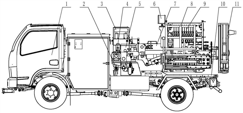
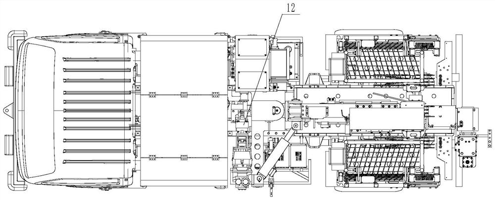
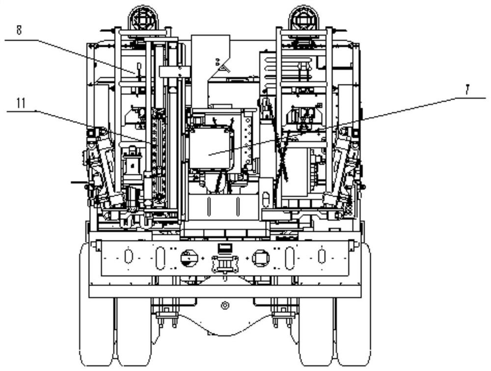
The invention discloses a dual-power hydraulic anchor rod drill carriage. The dual-power hydraulic anchor rod drill carriage comprises an electric vehicle chassis, a machine base part, a drill arm mechanism, an anchor rod machine, a working platform set, an operation table and a hydraulic system which is connected with the electric vehicle chassis, the drill arm mechanism, the anchor rod machine, the working platform set and the operation table and controls the actions of the electric vehicle chassis, the drill arm mechanism, the anchor rod machine, the working platform set and the operation table, the electric vehicle chassis is arranged at the bottom of the drill carriage, the machine base part is arranged on the electric vehicle chassis, a drilling arm mechanism is arranged on the machine base part, and a roof bolter, a working platform set and an operation table are arranged on the drilling arm mechanism; the hydraulic system is independently driven by two sets of power sources, and the two sets of power sources are an electric vehicle chassis transfer case driving hydraulic pump and a wind motor driving hydraulic pump respectively. The two sets of power sources which are independently driven are arranged, wind and electricity clean energy is used as power, the device is used for coal mine underground roadway repair, all-directional adjustment of the roof bolter and completion of supplementary driving of anchor rods and anchor cables, noise is low, zero pollution emission is achieved, the device conforms to the environment-friendly development concept of the green and low-carbon technology of coal mine machinery, and the device is wide in application prospect.

Description

technical field [0001] The invention relates to the field of rock bolters, in particular to a dual-power hydraulic rock bolter. Background technique [0002] At present, most of the roadway excavation of large and medium-sized coal mines adopts the operation method of anchor rod and anchor cable support. The shelf is used for operation, the operation efficiency is low, and the operation safety is poor. [0003] Moreover, most of the existing coal mine vehicle chassis are explosion-proof diesel engine trackless rubber-tyred vehicles, which are noisy and emit high levels of harmful gases, which do not conform to the development concept of green and low-carbon technology. [0004] This shows that above-mentioned existing rock bolter obviously still has inconvenience and defective in structure, method and use, and demands urgently further improving. How to create a new dual-power hydraulic rock bolter, which uses wind and electric clean energy as the power source, has low nois...

Claims


Application Information

Patent Timeline
IPC IPC(8): E21D20/00E21B7/02B66F11/04B66F13/00F15B11/16F15B13/06B60L50/60B60P3/00
CPCE21D20/003E21B7/02E21B7/023E21B7/026B66F11/046B66F13/00F15B11/16F15B13/06B60L50/60B60P3/00Y02T10/70
Inventor 闫子龙刘琦张馨刘昊吴明正余帅王旭东张涛
Owner LANG FANG JING LONG GRAND IND MACHINERY CO LTD
Learn More