


Quick Research
Generate reliable direction feasibility study reports for your R&D in just a few steps.

Technical Q&A
Discover and master advanced knowledge NOW. Basics, ideas, possibilities, all at once.

Find Solutions
As an expert in R&D theories, this can generate solutions to your technical problems instantly.

Evaluate Feasibility
Analyze your overall solution with one click, know your potential R&D risks in advance.

Monitor Landscape
Get weekly tech updates, stay abreast of the latest tech innovations and key insights.
Movable color steel tile cutting machine
A tile cutting machine and mobile technology, which is applied in the field of mobile color steel tile cutting machines, can solve the problems of no dust removal device, scratches by handling personnel, and affecting the operator's sight, and achieve the effect of protecting color steel tiles
- Summary
- Abstract
- Description
- Claims
- Application Information
AI Technical Summary
Problems solved by technology
Method used
Image

Examples
Embodiment 1
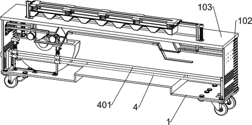
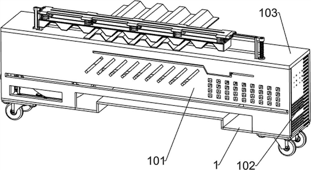
[0046] A mobile color steel tile cutting machine, such as Figure 1-7 As shown, it includes bottom plate 1, long cover plate 101, short cover plate 102, top plate 103, left bearing seat 2, right bearing seat 3, screw rod 4, sliding rod 401, reciprocating motor 5, screw nut 6, sliding sleeve 7 , cutting mechanism, jacking assembly and upper guide rail 24, with rollers under the base plate 1, short cover plates 102 connected to the left and right sides of the base plate 1, long cover plates 101 connected to the front and rear sides of the base plate 1, short cover plates 102 and long covers A top plate 103 is connected above the plate 101, and the long cover plate 101, the short cover plate 102 and the top plate 103 form the body shell, wherein the top plate 103 is a workbench, and the bottom of the bottom plate 1 is provided with rollers for easy movement. Bearing seat 2, the right bearing seat 3 is fixedly connected to the right side of the bottom plate 1 top, the screw rod 4 ...
Embodiment 2
[0049] On the basis of Example 1, such as Figure 4 As shown, the jacking assembly includes a jacking guide rail 8, a cavity 801, a jacking spring 9, a jacking slide seat 10, a jacking slider 11, a starting spring 12 and a starting button 13, and the two sliding sleeves 7 are fixed A jacking guide rail 8 is connected, and jacking springs 9 are sheathed on the jacking guide rail 8, and a cavity 801 is provided on the side wall of the jacking guide rail 8, and a starting spring 12 and a starting button 13 are arranged in the cavity 801, and the starting button 13 Fixedly connected with the starting spring 12, a jacking slide 10 is slidably connected to the top of the two jacking guide rails 8, the bottom of the jacking slide 10 is connected with the jacking spring 9, and one side of the jacking slide 10 is provided with a locking device. Through hole, when the jacking slide seat 10 and the jacking guide rail 8 are closed, the start button 13 snaps into the through hole for clamp...
Embodiment 3
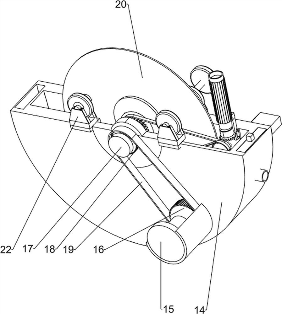
[0052] On the basis of Example 2, such as Figure 6 and Figure 7 As shown, the cutting mechanism includes a chainsaw casing 14, a cutting motor 15, a motor pulley 16, a rotating shaft 17, a housing pulley 18, a first belt 19, a saw blade 20 and a tightening bolt 21, and the jacking block 11 is fixedly connected Chainsaw casing 14, the jacking mechanism drives the cutting mechanism to rise through the jacking slider 11, the casing of the cutting motor 15 is fixedly connected on the rear side of the chainsaw casing 14, the motor pulley 16 is fixedly connected on the output shaft of the cutting motor 15, and the rotating shaft 17 The rotation is connected to the central part of the electric saw housing 14, the housing pulley 18 is fixedly connected on the rotating shaft 17, the first belt 19 is wound around the motor pulley 16 and the housing pulley 18, and can drive the rotating shaft 17 to rotate together when the cutting motor 15 rotates. The saw blade 20 is arranged on the ...
PUM
 Abstract
Description
Claims
Application Information
 - R&D Engineer
- R&D Manager
- IP Professional
- Industry Leading Data Capabilities
- Powerful AI technology
- Patent DNA Extraction
Browse by: Latest US Patents, China's latest patents, Technical Efficacy Thesaurus, Application Domain, Technology Topic, Popular Technical Reports.
© 2024 PatSnap. All rights reserved.Legal|Privacy policy|Modern Slavery Act Transparency Statement|Sitemap|About US| Contact US: help@patsnap.com