Vehicle projection lighting system for road indication
A lighting and vehicle technology, applied in the field of vehicle projection lighting system, can solve problems such as not being able to meet road indications, and achieve the effects of flexible use, clear image quality, and improved safety
- Summary
- Abstract
- Description
- Claims
- Application Information
AI Technical Summary
Problems solved by technology
Method used
Image

Examples
Embodiment 1
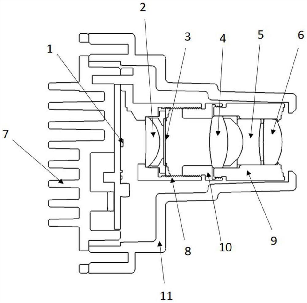
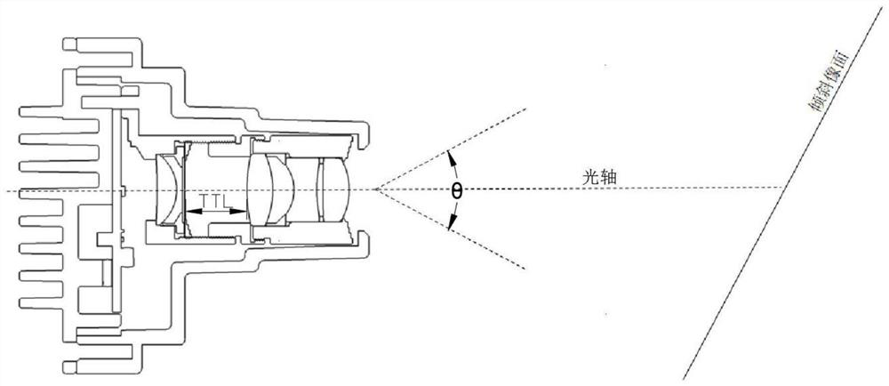
[0035] Embodiment 1: as Figure 5 , install the projected lighting system of this vehicle in the front air intake grille, the optical axis of the system deflects 28 degrees downward and 10 degrees outward, the power of light source 1 is 3 watts, along the optical axis from the side of light source 1 to the imaging side Set in turn:
[0036] A first lens 2 with positive refractive power, the first lens 2 is a condensing and collimating lens for converging the light emitted by the light source 1;
[0037] Film sheet 3, the modulated pattern is engraved on the film sheet 3; Figure 6 is the modulated steering arrow on film 3;
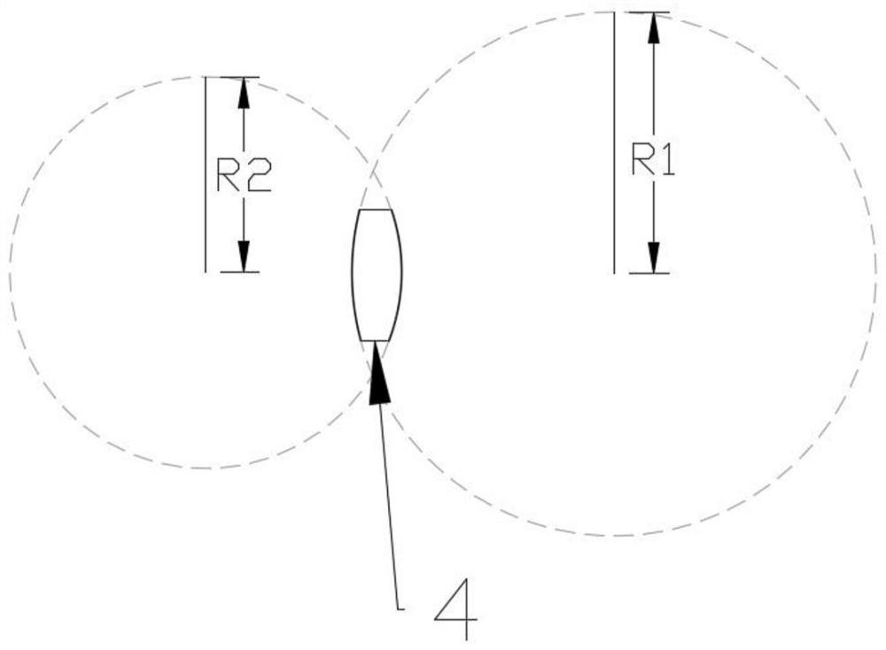
[0038] There is a second lens 4 with positive refractive power, and both sides of the second lens 4 are convex surfaces;
[0039] A third lens 5 with negative refractive power, both sides of the third lens 5 are concave;
[0040] There is a fourth lens 6 with positive refractive power, and both sides of the fourth lens 6 are convex surfaces;
[0041] ...
Embodiment 2
[0051] Embodiment 2: as Figure 5 , install the projected lighting system of this vehicle in the front air intake grille, the optical axis of the system deflects 28 degrees downward and 10 degrees outward, the power of light source 1 is 3 watts, along the optical axis from the side of light source 1 to the imaging side Set in turn:
[0052] A first lens 2 with positive refractive power, the first lens 2 is a condensing and collimating lens for converging the light emitted by the light source 1;
[0053] Film sheet 3, the modulated pattern is engraved on the film sheet 3; Figure 6 is the modulated steering arrow on film 3;
[0054] There is a second lens 4 with positive refractive power, and both sides of the second lens 4 are convex surfaces;
[0055] A third lens 5 with negative refractive power, both sides of the third lens 5 are concave;
[0056] There is a fourth lens 6 with positive refractive power, and both sides of the fourth lens 6 are convex surfaces;
[0057] ...
Embodiment 3
[0067] Embodiment 3: as Figure 5 , install the projected lighting system of this vehicle in the front air intake grille, the optical axis of the system deflects 28 degrees downward and 10 degrees outward, the power of light source 1 is 3 watts, along the optical axis from the side of light source 1 to the imaging side Set in turn:
[0068] A first lens 2 with positive refractive power, the first lens 2 is a condensing and collimating lens for converging the light emitted by the light source 1;
[0069] Film sheet 3, the modulated pattern is engraved on the film sheet 3; Figure 6 is the modulated steering arrow on film 3;
[0070] There is a second lens 4 with positive refractive power, and both sides of the second lens 4 are convex surfaces;
[0071] A third lens 5 with negative refractive power, both sides of the third lens 5 are concave;
[0072] There is a fourth lens 6 with positive refractive power, and both sides of the fourth lens 6 are convex surfaces;
[0073] ...
PUM
 Abstract
Description
Claims
Application Information
 - R&D
- Intellectual Property
- Life Sciences
- Materials
- Tech Scout
- Unparalleled Data Quality
- Higher Quality Content
- 60% Fewer Hallucinations
Browse by: Latest US Patents, China's latest patents, Technical Efficacy Thesaurus, Application Domain, Technology Topic, Popular Technical Reports.
© 2025 PatSnap. All rights reserved.Legal|Privacy policy|Modern Slavery Act Transparency Statement|Sitemap|About US| Contact US: help@patsnap.com