
Selective powder spreading device for selective laser melting forming of large thin-wall part

A technology of laser selective melting and large thin-walled parts, which is applied in the direction of improvement of process efficiency, additive manufacturing, energy efficiency, etc., can solve the problem of high forming cost of additive manufacturing of large thin-walled parts, and achieve the effect of good forming quality

Pending Publication Date: 2022-01-14
CAPITAL AEROSPACE MACHINERY
View PDF11 Cites 0 Cited by
  • Summary
  • Abstract
  • Description
  • Claims
  • Application Information

AI Technical Summary

Problems solved by technology

[0004] The technical problem solved by the invention is: to overcome the deficiencies of the prior art, to provide a selective powder spreading device for laser selective melting and forming of large thin-walled parts, and to solve the problem of high cost of additive manufacturing of large thin-walled parts

Method used


Image

  • Selective powder spreading device for selective laser melting forming of large thin-wall part
  • Selective powder spreading device for selective laser melting forming of large thin-wall part
  • Selective powder spreading device for selective laser melting forming of large thin-wall part

Examples


example 1

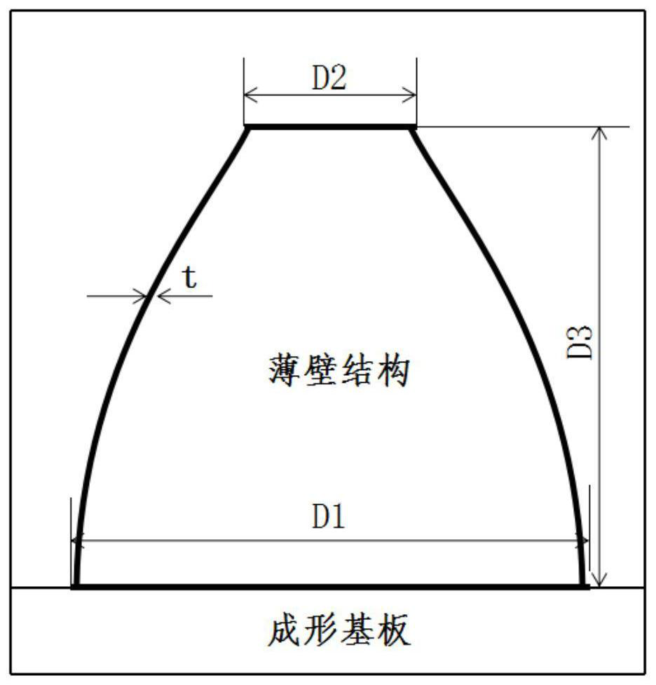
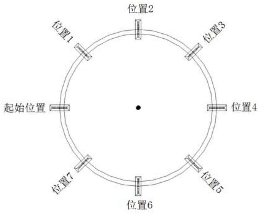
[0029] Taking the large thin-walled part A as an example, the diameter of the large end D1: 900mm, the diameter of the small end D2: 300mm, the shaft height D3 = 800mm, the wall thickness of the thin-walled part A = 5mm, and the width of the powder spreading is D4 = 15mm. The thickness is D6=0.1mm, the number of layers n=D3 / D6=800mm / 0.1mm=8000 layers; compare the data of a single layer of powder that needs to be laid, move the X and Y axes to carry out selective circular powder spreading on the substrate. The width of the first powder spreading is 15mm, the layer thickness is 0.1mm, and the substrate surface is a circle of 445mm, keeping 100 layers; layer; the i-th powdering, the substrate surface is a circle of 450-i*D4mm, and it is kept until the i*100th layer; repeat the above steps, the last powdering, the substrate surface is a circle with a diameter of D=150mm, until the first layer 8000 floors, the structural parts are formed.

example 2

[0031] Taking the large thin-walled part B as an example, the diameter of the large end D1: 1000mm, the diameter of the small end D2: 200mm, the shaft height D3 = 900mm, the wall thickness of the thin-walled part B is t = 8mm, and the powder spreading width is D4 = 16mm. The thickness is D6=0.2mm, the number of layers n=D3 / D6=(1000mm-200mm) / 0.2mm=4000 layers, compared with the single-layer data that needs to lay powder, move the X and Y axes to selectively circularize the substrate Spread the powder. The width of the first powder spreading is 16mm, the layer thickness is 0.2mm, the substrate surface is 484mm circular, and 80 layers are maintained; the second powder spreading width is 16mm, the substrate surface is 468mm circular, and 80 layers are maintained ;For the i-th powder spreading, the width value is 16mm, and the substrate surface is a circle with a diameter of 500-i*D4 mm, and it is maintained until the i*80 layer; repeat the above steps, and the last powder spreadin...


PUM

PropertyMeasurementUnit
Hole diameteraaaaaaaaaa
Diameteraaaaaaaaaa

Abstract

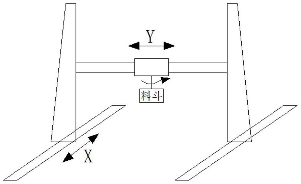
The invention discloses a selective powder spreading device for selective laser melting forming of a large thin-wall part. The selective powder spreading device comprises a hopper, guide rails and supporting beams, wherein the supporting beam is fixedly installed on the guide rails, and the hopper is hoisted below the supporting beam; the supporting beam can slide along the guide rails; the hopper can slide along the supporting beam; a plurality of through holes are formed in the bottom of the hopper forming cavity in the length direction; the hopper can perform circular motion in a horizontal plane around a lifting point; and the hopper is used for containing the additive manufacturing powder material of the structural part. The utilization rate of the powder material can be increased, and the additive manufacturing and forming cost of the large thin-wall part is saved.

Description

technical field [0001] The invention belongs to the technical field of laser selective melting and forming, in particular to a selective powder spreading device for laser selective melting and forming of large thin-walled parts. Background technique [0002] Large thin-walled components are important components of aerospace products, with a small end diameter of 300mm, a large end diameter of 900mm, and a shaft height of 800mm. The thin-walled components are densely arranged, the wall is thin, and the cross-section is variable. The width of the test piece is 6.0mm, and the average width of the weld seam reaches 4mm. The weld seam area accounts for more than 60% of the product surface area, and the deformation is large during welding. There are difficulties in the production of wall parts. [0003] For the additive manufacturing of large thin-walled parts, special large-scale equipment is used. On the equipment for laser selective melting, the powder scraper is supplied with...

Claims


Application Information

Patent Timeline
IPC IPC(8): B22F12/52B22F10/28B33Y30/00
CPCB22F12/52B22F10/28B33Y30/00Y02P10/25
Inventor 王国庆何京文梁晓康董鹏陈帅衣凤严振宇周庆军倪江涛梁丹佟玮何莎刘天亮孙国辉侯谊飞
Owner CAPITAL AEROSPACE MACHINERY
Learn More