Wide-angle RCS reduction metasurface based on radar wave absorption and scattering cancellation technology

A wide-angle, meta-surface technology, applied in the direction of antennas, electrical components, etc., can solve the problems of narrow angle reduction of incident electromagnetic waves and poor stability of angle reduction, and achieve the effect of realizing radar scattering cross section and improving angle stability

Active Publication Date: 2022-01-11
XIDIAN UNIV
View PDF14 Cites 15 Cited by
  • Summary
  • Abstract
  • Description
  • Claims
  • Application Information

AI Technical Summary

Problems solved by technology

However, this structure has the disadvantages of poor stability of the reduction angle and relatively narrow reduction angle of the incident electromagnetic wave.

Method used


Image

  • Wide-angle RCS reduction metasurface based on radar wave absorption and scattering cancellation technology
  • Wide-angle RCS reduction metasurface based on radar wave absorption and scattering cancellation technology
  • Wide-angle RCS reduction metasurface based on radar wave absorption and scattering cancellation technology

Examples


Embodiment 1

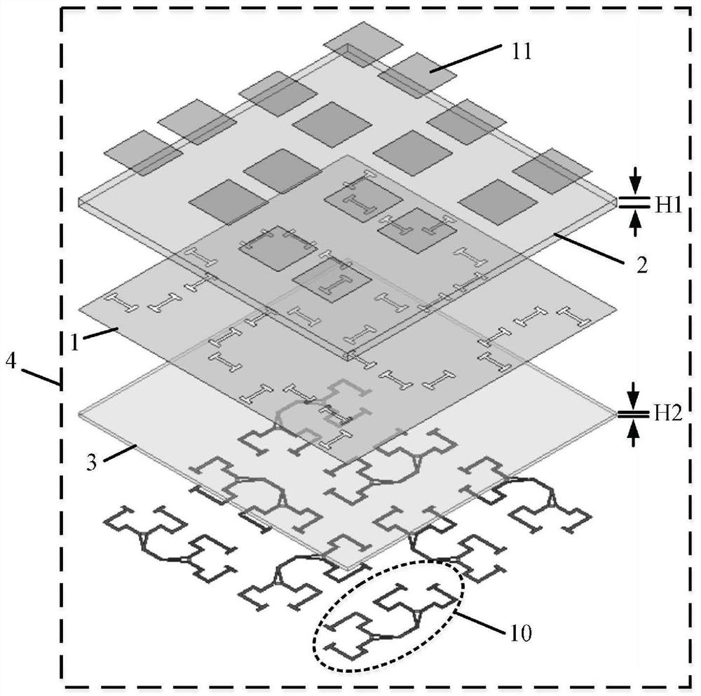
[0039] refer to figure 1 , the embodiment of the present invention includes an upper dielectric substrate 2, a metal floor 1, and a lower dielectric substrate 3. Radiation metal patches 11 are distributed on the upper surface of the upper dielectric substrate 2, and a microstrip feeder network 10 is distributed on the lower surface of the lower dielectric substrate 3; The wide-angle RCS reduction metasurface antenna array 4 is assembled according to the order of the upper dielectric substrate 2, the metal floor 1, and the lower dielectric substrate 3 from top to bottom.

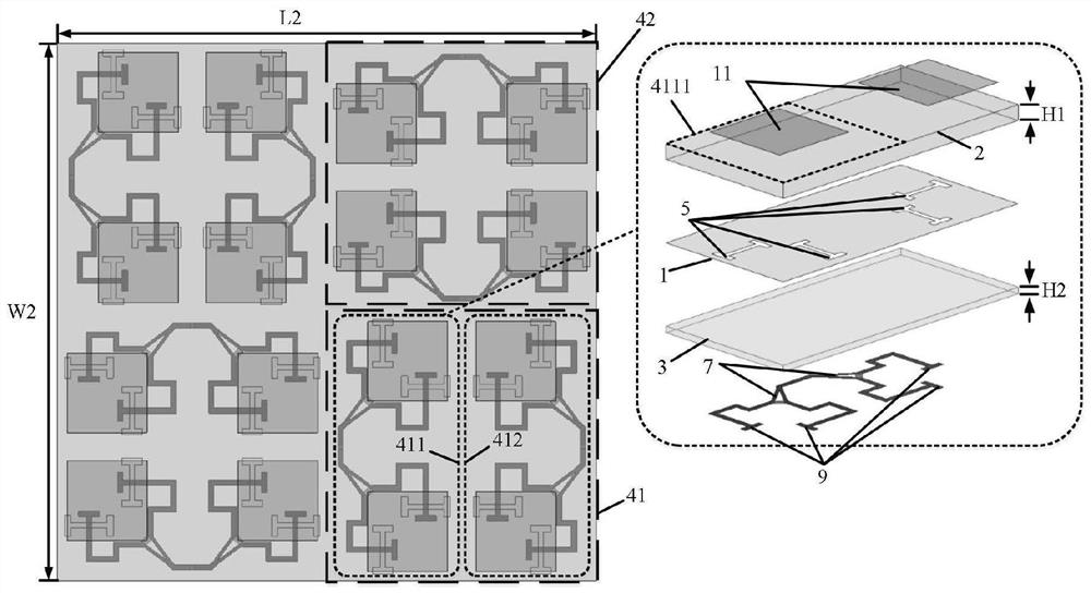
[0040] refer to figure 2 , the wide-angle RCS reduction metasurface antenna array 4 wherein the upper dielectric substrate 2 and the four radiating metal patches 11 and the lower dielectric substrate 3 and the upper two microstrip feeder networks 10 and the metal floor between them 1 Constitute the first microstrip dual-polarized antenna array 41, the upper dielectric substrate 2 adjacent to the first micro...

Embodiment 2

[0053] The structure of this embodiment is the same as that of Embodiment 1, and the following parameters have been adjusted:

[0054] The dielectric constant ε of the upper dielectric substrate 2 1 2.2, thickness H 1 1.5mm.

[0055] The dielectric constant ε of the lower dielectric substrate 3 2 10.2, thickness H 2 0.5mm.

[0056] The length L of the metal patch 11 g 8.7mm, width W g is 8.7mm.

[0057] The resistance value R of the lumped ohmic resistor 6 e into 75 ohms.

Embodiment 3

[0059] The structure of this embodiment is the same as that of Embodiment 1, and the following parameters have been adjusted:

[0060] The dielectric constant ε of the upper dielectric substrate 2 1 2.0, thickness H 1 is 1.2mm.

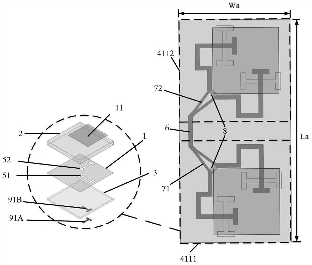
[0061] The length L of the first microstrip dual-polarized antenna array 411 a 40mm, width W a 20mm.

[0062] The length L of the metal patch 11 g 9.1mm, width W g It is 9.1mm.

[0063] The port phase difference between the first branch port 71B and the second branch port 71C of the first microstrip phase-shifting power divider 71 is θ 1 is 80°, the port phase difference between the third branch port 72B and the fourth branch port 72C of the second microstrip phase-shifting power divider 72 is θ 2 is 80°.

[0064] The resistance value R of the lumped ohmic resistor 6 e into 25 ohms.


PUM


Abstract

The invention belongs to the technical field of antenna RCS (radar cross section) reduction, and particularly relates to a wide-angle RCS reduction metasurface based on a radar wave absorbing and scattering cancellation technology. The metasurface is characterized by comprising an upper dielectric substrate (2), a metal floor (1) and a lower dielectric substrate (3), radiation metal patches (11) are distributed on the upper surface of the upper dielectric substrate (2). microstrip feeder networks (10) are distributed on the lower surface of the lower dielectric substrate (3), and the upper dielectric substrate (2), the metal floor (1) and the lower dielectric substrate (3) are combined from top to bottom to form the wide-angle RCS reduction metasurface antenna array (4). Different from the conception of the prior art, the metasurface design is carried out in a mode of combining radar wave absorption and scattering cancellation technologies, and a good reduction effect can be realized in a wide-angle electromagnetic wave incidence range.

Description

technical field [0001] The invention belongs to the technical field of antenna RCS reduction, and in particular relates to a wide-angle RCS reduction metasurface based on radar absorbing and scattering cancellation technology, which can be used in radar systems with higher requirements on scattering characteristics. Background technique [0002] Radar cross section (RCS) is the most critical concept in radar stealth technology, which characterizes a physical quantity of the echo intensity produced by the target under the irradiation of radar waves. With the continuous development of radar detection technology, radar stealth technology plays an increasingly important role in modern electronic information systems, especially in the field of secure communication, how to reduce the RCS characteristics of the platform itself and the antenna installed on the platform becomes very important. [0003] The RCS reduction methods in practical scenarios that have been widely studied an...

Claims


Application Information

Patent Timeline
Patent Type & Authority Applications(China)
IPC IPC(8): H01Q15/24H01Q17/00
CPCH01Q17/00H01Q15/24H01Q15/242
Inventor 史琰孟赞奎
Owner XIDIAN UNIV
Why Eureka
Try Eureka