Method and a system for separating hydrogen obtained by reforming

A separation method and separator technology, applied in hydrogen separation, chemical instruments and methods, hydrogen/synthesis gas production, etc., can solve the problem of increasing pressure drop between stages of reforming hydrogen supercharger, increasing cooling capacity and heat exchange recovery, public utility Problems such as increased project consumption, to achieve the effect of low outlet pressure, low cooling load, and reduced cooling load

Active Publication Date: 2022-01-11
CHINA PETROLEUM & CHEM CORP +2
View PDF6 Cites 0 Cited by
  • Summary
  • Abstract
  • Description
  • Claims
  • Application Information

AI Technical Summary

Problems solved by technology

In the recontact process, the reformed hydrogen is compressed in two or three stages (cooling and separation facilities are installed between the stages), and then mixed with the oil phase at the bottom of the reaction product separator, cooled, and cryogenically entered into the absorption tower to purify hydrogen and improve liquid recovery. The absorption temperature is 0°C, but the disadvantage is: the recontact tank operates at 0°C, and the cooling capacity of the material at the top and bottom of the adsorption tower needs to be recovered, and the recontact cold oil is set to exchange heat with the outlet (or inlet) of the first stage of the reforming hydrogen booster , and set the heat exchange between the re-contacting cold hydrogen and the feed of the adsorption tower, the heat exchange process is complicated; increasing the heat exchange recovery of the cooling capacity will lead to an increase in the pressure drop between the stages of the reforming hydrogen booster, and the corresponding increase in the consumption of public works, and its energy consumption Compared with the comparison process, only 151kg standard oil / h is reduced, and the energy saving effect is not obvious

Method used


Image

  • Method and a system for separating hydrogen obtained by reforming

Examples


Embodiment Construction

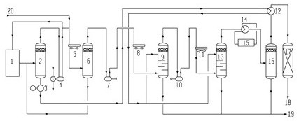
[0030] Such as figure 1As shown, a reforming hydrogen separation system includes a reaction product separator 2, a liquid separation tank 6 at the inlet of a reforming hydrogen booster, a first-stage recontacting tower 9, a second-stage recontacting tower 13, and a reforming hydrogen separator Tank 16 and reforming hydrogen dechlorination tank 17, the reaction product separator 2 is provided with the product inlet of the whole reaction system 1, the top outlet of the reaction product separator 2 is connected to the reforming cycle hydrogen compressor 4, and the reforming cycle hydrogen compressor 4 outlets are respectively connected to the top inlet of the reforming reaction system 1 and the liquid separation tank 6 at the inlet of the reforming hydrogen booster, and the bottom outlet of the reaction product separator 2 is respectively connected to the upper part of the first-stage recontact tower 9 and the second stage through the reforming hydrogen heat exchanger 12. The upp...


PUM


Abstract

The invention discloses a method and a system for separating hydrogen obtained by reforming, which are used for improving the purity of the hydrogen obtained by reforming, improving the liquid yield and further reducing the energy consumption of a device. The system mainly comprises a reaction product separator, a reforming hydrogen supercharger inlet liquid separation tank, a first-section recontact tower, a second-section recontact tower, a reforming hydrogen liquid separation tank and a reforming hydrogen dechlorination tank, wherein a top outlet of the reaction product separator is connected with a reforming recycle hydrogen compressor; an outlet of the reforming recycle hydrogen compressor is connected with the reforming hydrogen supercharger inlet liquid separation tank; an outlet in the bottom of the reaction product separator is respectively connected with the upper part of the first-section recontact tower and the upper part of the second-section recontact tower through a reforming hydrogen heat exchanger; and an outlet in the top of the reforming hydrogen supercharger inlet liquid separation tank is connected with the lower part of the first-section recontact tower through a reforming hydrogen supercharger first section and a first-section recontact air cooler in sequence; a top outlet of the first-section recontact tower is connected with the lower part of the second-section recontact tower through a reforming hydrogen supercharger second section and a second-section re-contact air cooler in sequence; a top outlet of the second-section recontact tower is connected with the reforming hydrogen liquid separation tank, and a top outlet of the reforming hydrogen liquid separation tank is connected with the reforming hydrogen dechlorination tank through the reforming hydrogen heat exchanger.

Description

technical field [0001] The invention belongs to the field of petrochemical industry or natural gas chemical industry, and specifically relates to a reforming hydrogen separation method and system, which improves the recovery rate of hydrogen, simplifies the heat exchange process, and reduces the energy consumption of the device. Background technique [0002] Catalytic reforming is one of the main processes of petroleum refining, and its main products are reformed gasoline rich in aromatics and reformed hydrogen. Reformed gasoline is mainly used as a high-octane gasoline blending component or to produce aromatic products such as benzene, toluene, and xylene; reformed hydrogen is the main source of hydrogen for various hydrogenation units in refineries, and its price is low. In the past ten years, in order to meet the huge demand for aromatics raw materials and hydrogen in downstream units and improve the economic benefits of the units, the number of new catalytic reforming un...

Claims


Application Information

Patent Timeline
Patent Type & Authority Applications(China)
IPC IPC(8): C10L3/12C01B3/50
CPCC10L3/12C01B3/50C01B2203/048
Inventor 李爱国郭劲鹤徐又春董海芳寇肖张钟岩王子阅李辰骁栋冯雯
Owner CHINA PETROLEUM & CHEM CORP
Why Eureka
Try Eureka