Amphibious micro-robot with deformable wheels
A micro-robot, amphibious technology, applied to amphibious vehicles, wheels, motor vehicles, etc., can solve the problems of unfavorable lightweight development of robots, complex design structure, etc., achieve rich motion modes, simple and compact structure, and reduce the weight of the whole machine Effect
- Summary
- Abstract
- Description
- Claims
- Application Information
AI Technical Summary
Problems solved by technology
Method used
Image
Examples
Embodiment 1
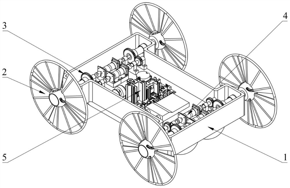
[0067] The present invention provides an amphibious micro-robot with deformable wheels, comprising a frame 1, a deformable wheel 2, a transmission system 3, a drive system 4 and a control system 5, the frame 1 is used for bearing; the deformable wheel 2 is installed on The state on the frame 1 and itself can be switched to match the movement in the amphibious environment; the drive system 4 can drive the deformable wheel 2 to act through the transmission system 3, wherein the action includes the switching of the state of the deformable wheel 2 and / or Drive the deformable wheel 2 to rotate; the control system 5 controls and connects the drive system 4 .
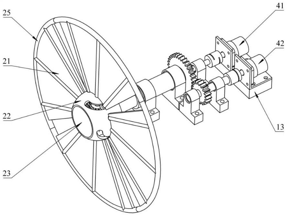
[0068] Further, the deformable wheel 2 includes an integral spoke 21 and a hollow hub 22, the integral spoke 21 includes a first connecting column 26, a central column 24 and a second connecting column 27, the hollow hub 22 includes a first arc-shaped hole 29, a central The through hole 28 and the second arc-shaped hole 30, th...
Embodiment 2
[0077] In this example, if Figure 1 to Figure 9 As shown, four independent deformable wheels 2 are arranged symmetrically on both sides of the frame 1, the drive system 4 is connected to the deformable wheels 2 through the transmission system 3, and the control system 5 is connected to the drive system 4 to realize the deformation and rotation speed of the deformable wheels 2 control.
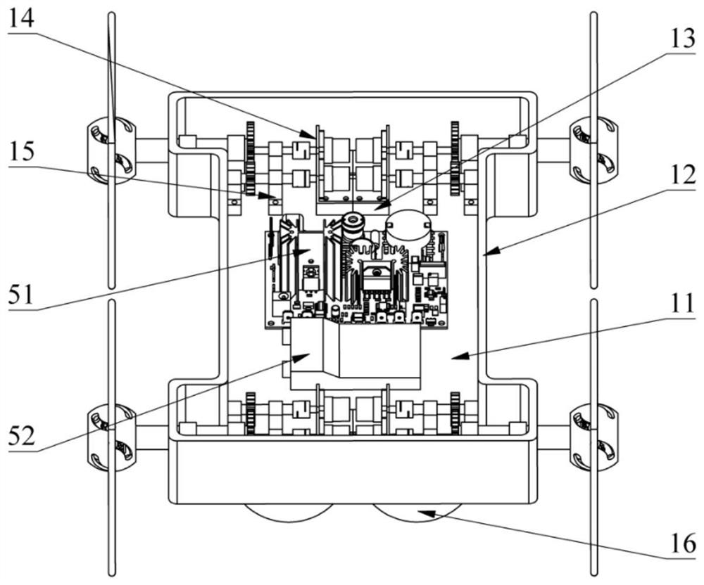
[0078] Such as figure 2 As shown, the base 11 and the partition 12 are connected to form a sealed space, the riser 13 and the support unit 15 are fixed on the base 11 , the motor base 14 is fixed on the riser 13 , and the buoyancy unit 16 is fixed on the bottom of the base 11 . The control system 5 of the present invention includes a main control board 51 and a battery 52, and is controlled by PID. Both the deforming motor 41 and the rotating motor 42 have their own angular displacement sensors, which can form a closed-loop control with the control system 5 .
[0079] Such as image 3 , ...
PUM
 Abstract
Description
Claims
Application Information
 - R&D Engineer
- R&D Manager
- IP Professional
- Industry Leading Data Capabilities
- Powerful AI technology
- Patent DNA Extraction
Browse by: Latest US Patents, China's latest patents, Technical Efficacy Thesaurus, Application Domain, Technology Topic, Popular Technical Reports.
© 2024 PatSnap. All rights reserved.Legal|Privacy policy|Modern Slavery Act Transparency Statement|Sitemap|About US| Contact US: help@patsnap.com


