Engine combustion chamber structure, engine and fire pump

A combustion chamber and engine technology, which is applied to combustion engines, engine components, machines/engines, etc., can solve the problems of reduced engine life, poor heat dissipation, damage, etc., to prevent excessive temperature, good cooling effect, and guarantee The effect of the cooling effect

Inactive Publication Date: 2022-01-07
SHANDONG UNIV +1
View PDF6 Cites 0 Cited by
  • Summary
  • Abstract
  • Description
  • Claims
  • Application Information

AI Technical Summary

Problems solved by technology

[0003] At present, the fire pump uses a single-cylinder engine as the power source. The single-cylinder engine converts heat energy into mechanical energy, so that the fire pump can provide fluid with a set pressure. When the single-cylinder engine is working, the shell temperature will rise accordingly, especially for high-pressure and high-speed engines. It will be damaged due to overheating in a high temperature state. At present, there is a water pump engine whose casing is composed of two casings and a casing cover, one of which is used to install components such as the crankshaft, and the other casing is used as a combustion chamber. The air inlet and the exhaust port are set, the shell cover seals the space formed by the two shells, and a spark plug is set. When the engine is cooled down, a cooling fin is set on the shell to dissipate heat through air convection. The inventor It was found that the heat dissipation effect of this method is not good. After a certain period of use, the temperature of the combustion chamber is very high, which reduces the service life of the engine

Method used


Image

  • Engine combustion chamber structure, engine and fire pump
  • Engine combustion chamber structure, engine and fire pump
  • Engine combustion chamber structure, engine and fire pump

Examples


Embodiment 1

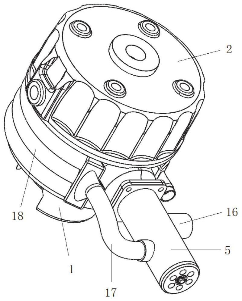
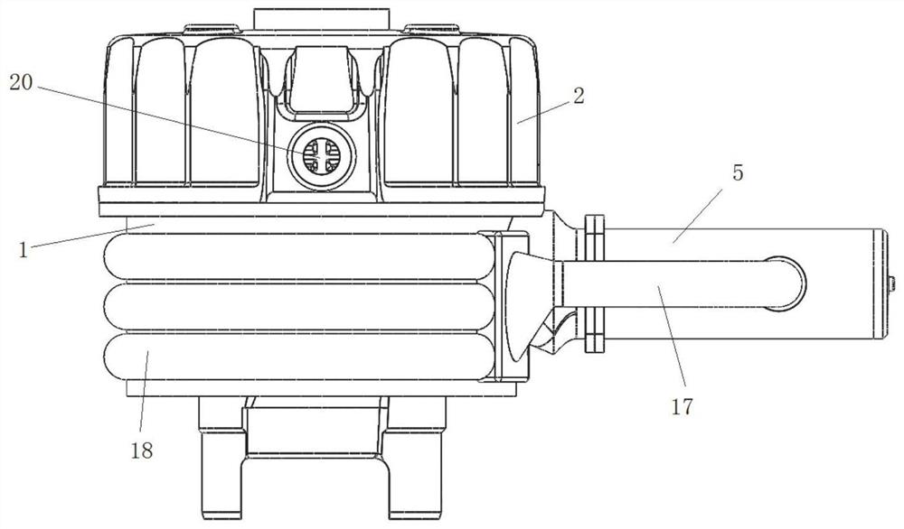
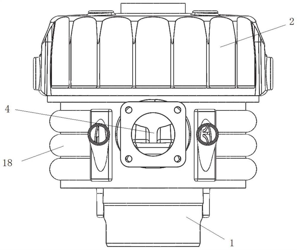
[0034] This embodiment provides a kind of engine combustion chamber structure, is used for the engine of fire pump, as Figure 1-Figure 4 As shown, the combustion chamber structure includes a combustion chamber cylinder block 1, and there is a space for fuel combustion inside the combustion chamber cylinder block. One end of the combustion chamber cylinder block is buckled and fixed with a cavity cover 2, and the cavity cover is used to align the combustion chamber cylinder body. One end of the body is open and closed. A fuel injection plug is installed on the chamber cover for injecting fuel into the combustion chamber.

[0035] The combustion chamber cylinder includes a first cylinder part 1-1 and a second cylinder part 1-2 integrally connected, and an air inlet 3 and an exhaust port 4 are opened on the second cylinder part.

[0036] The above structure is the same as that of the existing fire pump engine combustion chamber, and this embodiment is an improvement on the exis...

Embodiment 2

[0063] This embodiment provides an engine, which is provided with the engine combustion chamber structure described in Embodiment 1. Other structures of the engine may adopt the structure of an existing fire pump engine, and will not be described in detail here.

Embodiment 3

[0065] This embodiment provides a fire pump, which is installed with the engine described in Embodiment 2. The other structures of the fire pump can be those of the existing fire pump, and will not be described in detail here.


PUM


Abstract

The invention relates to an engine combustion chamber structure, an engine and a fire pump. The engine combustion chamber structure comprises a combustion chamber cylinder block and a chamber cover buckled on the combustion chamber cylinder block, and an exhaust port of the combustion chamber cylinder block is provided with a ventilation pipeline; a rotating shaft coaxial with the ventilation pipeline is arranged in the ventilation pipeline, and the rotating shaft penetrates through a separator arranged in the ventilation pipeline; the ventilation pipeline is divided into a first cavity and a second cavity by the separator, and the first cavity is arranged close to the exhaust port; the end, located in the first cavity, of the rotating shaft is provided with a plurality of first fan blades, and the end, located in the second cavity, of the rotating shaft is provided with a plurality of second fan blades; the first cavity communicates with the exhaust pipe, and the second cavity is provided with an air inlet; and the second cavity communicates with an air cooling pipeline arranged on the periphery of the combustion chamber cylinder block through the ventilation pipe. The combustion chamber is good in heat dissipation effect.

Description

technical field [0001] The invention relates to the technical field of fire pumps, in particular to an engine combustion chamber structure, an engine and a fire pump. Background technique [0002] The statements herein merely provide background information related to the present invention and do not necessarily constitute prior art. [0003] At present, the fire pump uses a single-cylinder engine as the power source. The single-cylinder engine converts heat energy into mechanical energy, so that the fire pump can provide fluid with a set pressure. When the single-cylinder engine is working, the shell temperature will rise accordingly, especially for high-pressure and high-speed engines. It will be damaged due to overheating in a high temperature state. At present, there is a water pump engine whose casing is composed of two casings and a casing cover, one of which is used to install components such as the crankshaft, and the other casing is used as a combustion chamber. The...

Claims


Application Information

Patent Timeline
Patent Type & Authority Applications(China)
IPC IPC(8): F02B23/00F02F1/04F02F1/14F04D13/02
CPCF02B23/00F02F1/04F02F1/14F04D13/02Y02T10/12
Inventor 张建华葛英尚郑德璞朱康逸宋国豪
Owner SHANDONG UNIV
Why Eureka
Try Eureka