Air-cooled metal separator for fuel cell and fuel cell stack using same

A fuel cell stack and metal separation technology, which is applied to fuel cell grouping, fuel cell components, fuel cells, etc., can solve the problems of difficulty in making a graphite cooling flow path and increase the stack volume, and achieve effective cooling. Structure, the effect of preventing deformation

Active Publication Date: 2012-05-23
HYUNDAE STEEL CO LTD
View PDF6 Cites 4 Cited by
  • Summary
  • Abstract
  • Description
  • Claims
  • Application Information

AI Technical Summary

Problems solved by technology

But in this case, there is a disadvantage that as the volume of the separation plate becomes larger, the volume of the stack also becomes larger
[0012] In addition, in the case of the separation plate formed by molding a thin metal plate, it is difficult to separately manufacture a cooling channel similar to graphite

Method used


Image

  • Air-cooled metal separator for fuel cell and fuel cell stack using same
  • Air-cooled metal separator for fuel cell and fuel cell stack using same
  • Air-cooled metal separator for fuel cell and fuel cell stack using same

Examples


Embodiment Construction

[0029] Hereinafter, an air-cooled metal separator plate for a fuel cell according to the present invention and a fuel cell stack using the same will be described in detail with reference to the drawings.

[0030] In the description process, the thickness of the lines or the size of the structural elements shown in the drawings will be exaggerated for the clarity and convenience of the description.

[0031] In addition, the terms used in the present invention are defined in view of their functions in the present invention, and the interpretation of these terms may vary depending on the user's or operator's intention or custom.

[0032] Therefore, the definitions of these terms should be based on the entire contents of this specification.

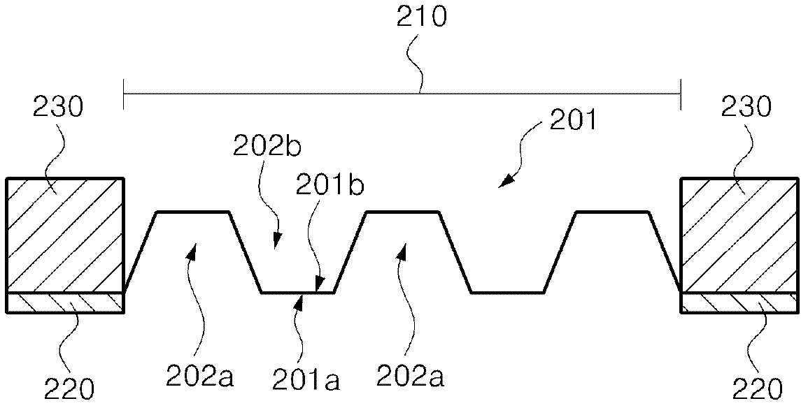
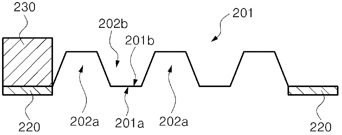
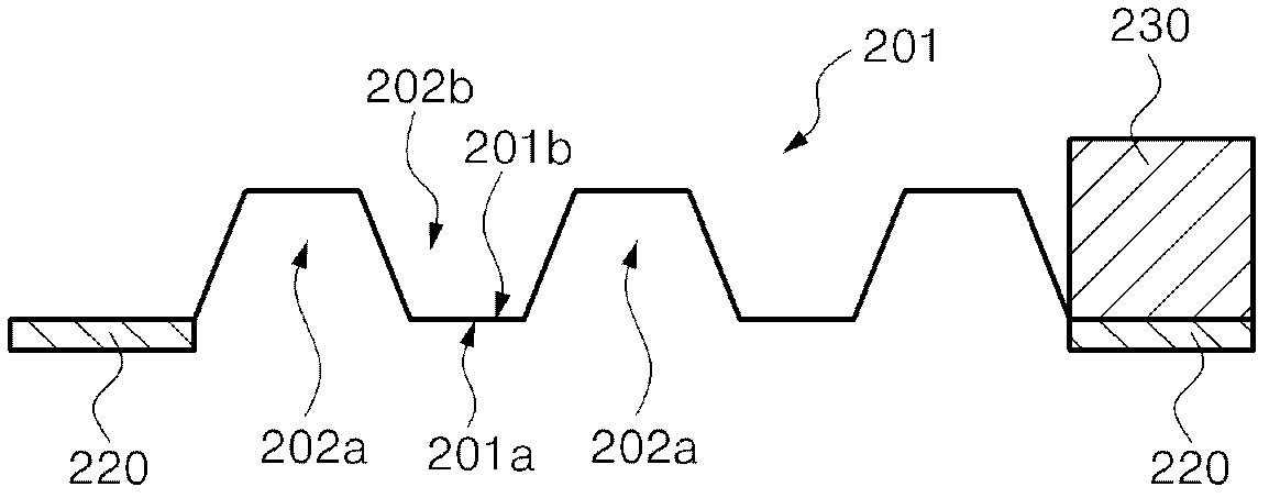
[0033] Figure 1 to Figure 4 An air-cooled metal separator plate for a fuel cell according to an embodiment of the present invention is schematically shown.

[0034] The air-cooled metal separator plate of the present invention includes a ch...


PUM


Abstract

Disclosed is an air-cooled metal separator which does not require cooling water. The air-cooled metal separator according to the present invention comprises: a channel part which includes reactive gas channels protruded from a front side to a back side at the center of a metal plate, and air flow passages formed between the reactive gas channels protruded to the back side; a first gasket which is continuously formed at the edge of the front side of the channel part; and a second gasket which is non-continuously formed at the edge of the back side of the channel part, wherein the non-continuous part serves as an air movement passage.

Description

technical field [0001] The present invention relates to a metal separator (Metal Separator) for a fuel cell, and more particularly relates to a non-continuous spacer that can be used to support a moving passage of air and a separator without supplying cooling water by means of air cooling (gasket) air-cooled metal separator plate. Background technique [0002] A fuel cell refers to a battery that directly converts chemical energy generated by fuel oxidation into electrical energy. Recently, in order to overcome the depletion of fossil fuels, the greenhouse effect caused by carbon dioxide, etc., and global warming, many researches such as solar cells are being carried out. [0003] Generally, a fuel cell converts chemical energy into electrical energy by utilizing the oxidation and reduction reactions of hydrogen and oxygen. At the negative electrode, hydrogen gas is oxidized and separated into hydrogen ions and electrons, and the hydrogen ions move to the positive electrod...

Claims


Application Information

Patent Timeline
Patent Type & Authority Applications(China)
IPC IPC(8): H01M8/02H01M8/24
CPCH01M8/0258H01M2008/1095H01M8/0267H01M8/0206H01M8/0273H01M8/2465Y02E60/50H01M8/0276H01M8/241H01M8/2483H01M8/02H01M8/24
Inventor 金基贞全俞铎
Owner HYUNDAE STEEL CO LTD
Why Eureka
Try Eureka