Injection molding machine mold with rapid condensation and separation mechanism

A condensation separation and injection molding machine technology, which is applied in the field of injection molding machine molds, can solve the problems of low cooling and demoulding efficiency, low production efficiency, and low safety, so as to improve condensation molding efficiency, injection molding efficiency, and internal Fluid effect

Pending Publication Date: 2022-01-07
东台市强圣精密铸造有限公司
View PDF6 Cites 0 Cited by
  • Summary
  • Abstract
  • Description
  • Claims
  • Application Information

AI Technical Summary

Problems solved by technology

[0005] The technical problem to be solved by the present invention is: in order to solve the problems existing in the above-mentioned background technology, an improved injection molding machine mold with a rapid condensation and separation mechanism is provided to solve the problem that the traditional injection molding machine has a simple structure and mainly adopts an upper opening mold. Manual operation is required after demolding, the efficiency of cooling and demoulding is not high, the method is single, and the safety is not high, and the operation is troublesome, resulting in the problem of low production efficiency

Method used


Image

  • Injection molding machine mold with rapid condensation and separation mechanism
  • Injection molding machine mold with rapid condensation and separation mechanism
  • Injection molding machine mold with rapid condensation and separation mechanism

Examples


Embodiment Construction

[0023] The present invention is described in further detail now in conjunction with accompanying drawing. These drawings are all simplified schematic diagrams, which only illustrate the basic structure of the present invention in a schematic manner, so they only show the configurations related to the present invention.

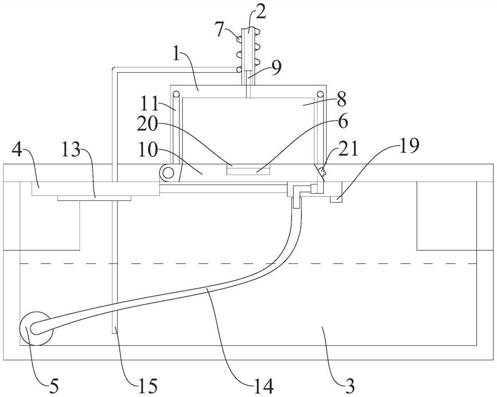
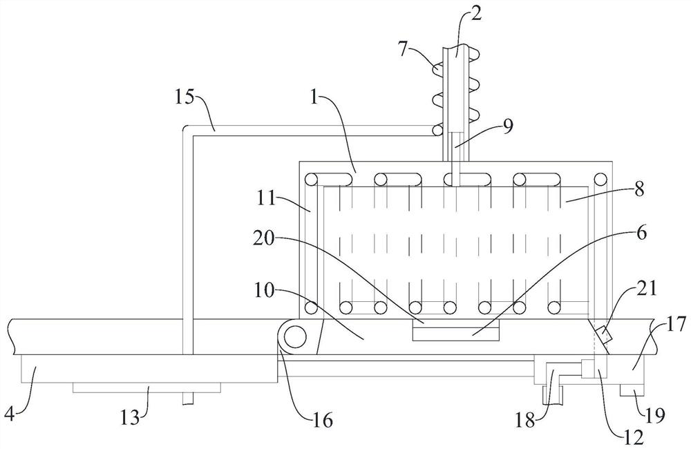
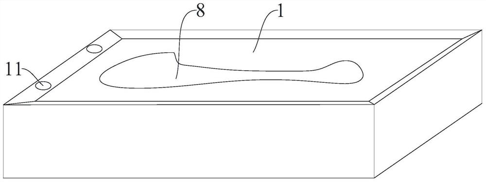
[0024] figure 1 , figure 2 and image 3 A mold for an injection molding machine with a rapid condensation separation mechanism is shown, including a mold body 1, an external material guide pipe 2 connected to the outlet of the injection molding machine, a bottom cooling tank 3 filled with condensed water inside, an electric telescopic machine 4, Liquid suction pump 5, pressure sensing control module 6 for controlling electric telescopic machine 4 and heat-conducting copper pipe 7 for transporting high-temperature steam. The lower surface of mold body 1 is provided with an internal molding groove 8 with a built-in injection molding cavity. 1. The upper end ...


PUM


Abstract

The invention relates to the technical field of injection molding equipment, in particular to an injection molding machine mold with a rapid condensation and separation mechanism. The injection molding machine mold comprises a mold body, an external material guide pipe externally connected with a discharge port of an injection molding machine, a bottom cooling tank containing condensate water, an electric telescoping device, a suction pump, a pressure sensing control module used for controlling the electric telescoping device, and a heat-conducting copper pipe used for conveying high-temperature steam. According to the injection molding machine mold with the rapid condensation and separation mechanism, an underneath opening mode is adopted, the electric telescoping device is used for controlling a movable sealing cover plate to control an opening in the lower end of an internal forming groove, the demolding efficiency of the mold is greatly improved, the mold body directly falls into the bottom cooling tank containing the condensate water, and the safety of demolding is improved; the condensate water is guided into an internal condensation flow channel of a snake-shaped structure on the periphery of the internal forming groove through the suction pump, so that the condensation forming efficiency is improved, and the injection molding efficiency is greatly improved; and the internal fluidity of the discharge end of the injection molding machine is greatly improved, and the injection molding efficiency is improved.

Description

technical field [0001] The invention relates to the technical field of injection molding equipment, in particular to an injection molding machine mold with a rapid condensation separation mechanism. Background technique [0002] Injection molding machine is also known as injection molding machine or injection machine. It is the main molding equipment for making thermoplastics or thermosetting plastics into various shapes of plastic products using plastic molding molds. [0003] Injection molding machines on the market can be divided into vertical, horizontal and all-electric. The injection molding machine heats the plastic, applies high pressure to the molten plastic, and makes it shoot out to fill the mold cavity. [0004] The traditional injection molding machine has a simple structure and mainly adopts an upper-opening mold. After cooling and demoulding, manual operation is required. The cooling and demoulding efficiency is not high, the method is single, and the safety...

Claims


Application Information

Patent Timeline
Patent Type & Authority Applications(China)
IPC IPC(8): B29C45/26B29C45/73B29C45/17
CPCB29C45/26B29C45/73B29C45/17
Inventor 王增明王陈炫陈栋周尚荣
Owner 东台市强圣精密铸造有限公司
Why Eureka
Try Eureka