Surgical linear cutting anastomat
A linear cutting and stapler technology, applied in the field of medical devices, can solve problems such as the inability to temporarily and quickly change the end of the stapler, the movement of the device body, and the inconvenient operation of adjusting the angle, so as to improve the fixed installation effect, good suture effect, Guaranteed stitching effect
- Summary
- Abstract
- Description
- Claims
- Application Information
AI Technical Summary
Problems solved by technology
Method used
Image
Examples
Embodiment 1
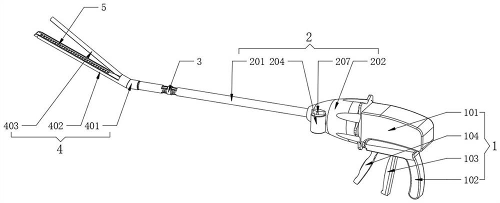
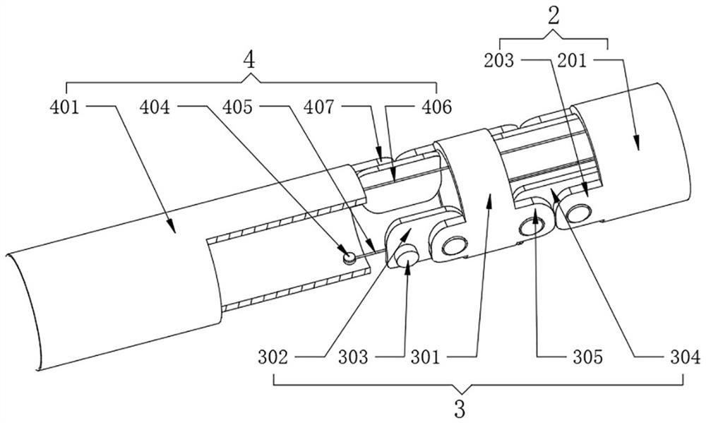
[0037] see Figure 1-2 as well as Figure 5 , a surgical linear cutting stapler, comprising a control handle 1, a rotator body 2, an adapter assembly 3 and an apparatus head assembly 4;
[0038] refer to figure 1 The rotator body 2 is rotated and assembled on one end of the control handle 1, and the adapter assembly 3 is rotatably assembled on the other end of the rotator body 2 away from the control handle 1. The body 2 also includes a main body 201, and the head assembly 4 also includes a head pipe 401. The inner part of the main body 201 and the head pipe 401 close to each other is assembled with a spacer 6, and the other end of the head pipe 401 is fixed. A staple cartridge case 402 is provided, the other end of the staple cartridge case 402 is rotated and assembled with a nail plate 403, the staple cartridge case 402 fits with the nail plate 403, and the nail cartridge case 402 is movably assembled with a movable nail cartridge 5.
[0039] refer to figure 1, the contr...
Embodiment 2
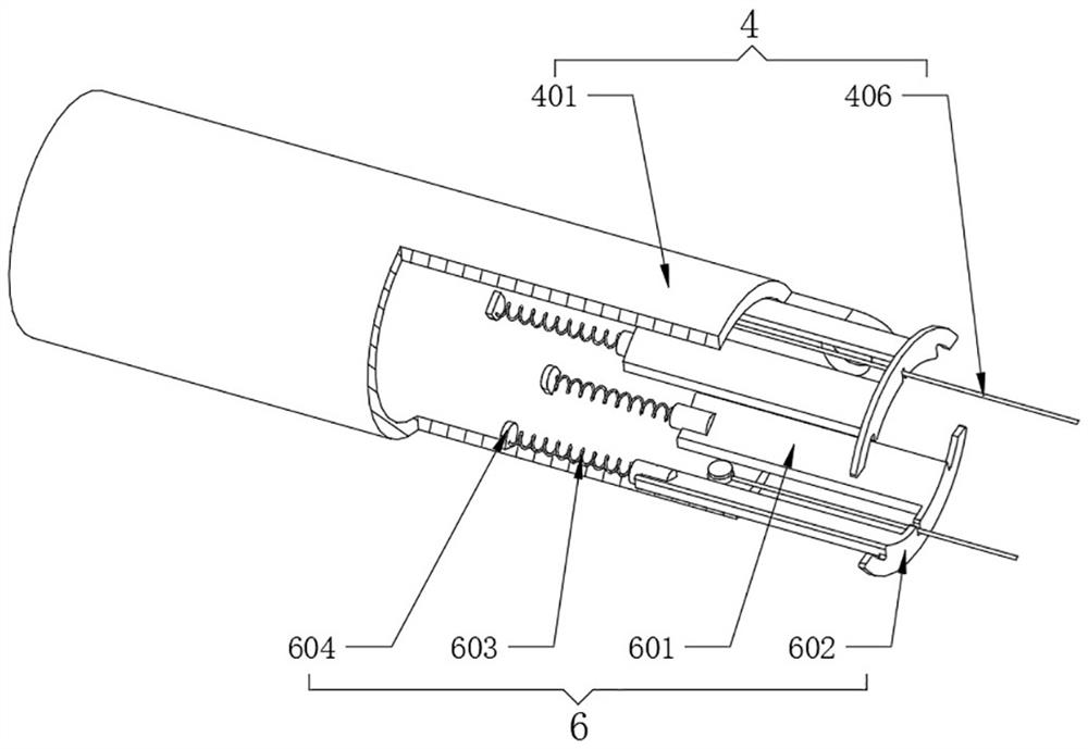
[0045] see Figure 3-4 , a surgical linear cutting stapler, comprising a control handle 1, a rotator body 2, an adapter assembly 3 and an apparatus head assembly 4;
[0046] refer to image 3 and Figure 4 The spacer 6 also includes an end plate 602, and both ends of one side of the end plate 602 are fixedly welded with an inner arc plate 601, and four sets of inner arc plates 601 are respectively symmetrically inserted into the main body 201 and the inside of the head pipe 401, During the rotation of the head tube 401, the end plate 602 will be squeezed from the transfer tube 301, the inner wall of the main body 201 and the head tube 401 is fixedly provided with an inner stopper 604, and the other end of the inner arc plate 601 is fixed. A spring 603 connected to the inner block 604 is fixedly connected, and the inner arc plate 601 will move inside the main device body 201 or the head tube 401, and at the same time cooperate with the inner block 604 to squeeze the spring 60...
Embodiment 3
[0049] see Figure 6-7 , a surgical linear cutting stapler, comprising a control handle 1, a rotator body 2, an adapter assembly 3 and an apparatus head assembly 4;
[0050] refer to Figure 6 , the movable staple bin 5 also includes a staple case 501, the middle of the staple case 501 is fixed with a blade groove 503 inside, and the inside of the staple case 501 is located on both sides of the blade groove 503 and is equidistantly provided with nail grooves 502, and the nails in different vertical rows The grooves 502 are arranged in steps, and the length and dimension of the staples located on the outside gradually increase. Cooperating with the nail grooves 502 arranged in steps, the thickness of the suture can be gradually increased from the center of the suture to both sides, thereby avoiding damage caused by the pulling between tissues. A phenomenon that causes the edge of a seam to crack.
[0051] refer to Figure 7 , the inner walls of the nail grooves 502 are fixed...
PUM
 Abstract
Description
Claims
Application Information
 - R&D
- Intellectual Property
- Life Sciences
- Materials
- Tech Scout
- Unparalleled Data Quality
- Higher Quality Content
- 60% Fewer Hallucinations
Browse by: Latest US Patents, China's latest patents, Technical Efficacy Thesaurus, Application Domain, Technology Topic, Popular Technical Reports.
© 2025 PatSnap. All rights reserved.Legal|Privacy policy|Modern Slavery Act Transparency Statement|Sitemap|About US| Contact US: help@patsnap.com


