
Motion compensation method and module, chip, electronic equipment and storage medium

A technology of motion compensation and motion vector, which is applied in TV, color TV, electrical components, etc., can solve problems such as halos easily, and achieve the effect of improving halos easily

Pending Publication Date: 2021-12-31
AMOLOGIC (SHANGHAI) CO LTD
View PDF0 Cites 0 Cited by
  • Summary
  • Abstract
  • Description
  • Claims
  • Application Information

AI Technical Summary

Problems solved by technology

[0006] The problem to be solved by the embodiment of the present invention is to provide a motion compensation method and module, chip, electronic device and storage medium to improve the problem that the edge of the moving object is prone to halo

Method used


Image

  • Motion compensation method and module, chip, electronic equipment and storage medium
  • Motion compensation method and module, chip, electronic equipment and storage medium
  • Motion compensation method and module, chip, electronic equipment and storage medium

Examples


Embodiment Construction

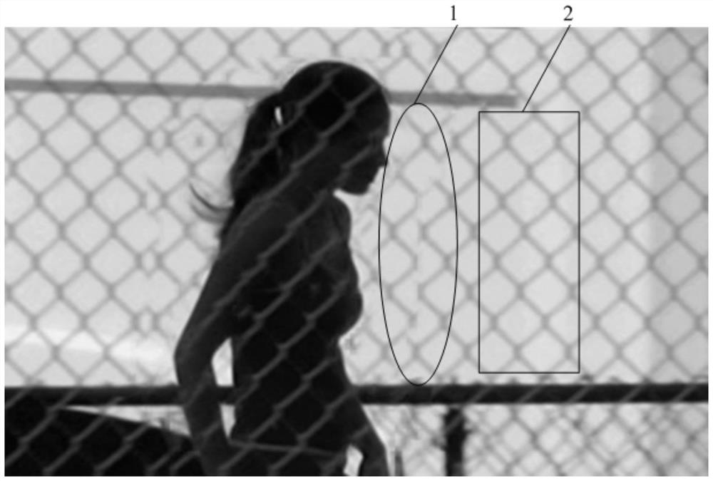
[0025] It can be seen from the background art that there is a halo effect in video images with moving objects at present. The reason for the halo is analyzed below in combination with images of adjacent frames.

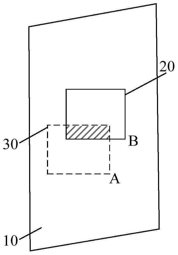
[0026] figure 2 It is the position relationship diagram of moving objects in adjacent frames, and it is a schematic diagram of superimposing the previous frame and the current frame. In the figure, the square frame is shifted from the A position of the background 10 to the B position, and the solid line square frame 20 represents the position of the moving object in the foreground of the current frame, and the solid line square frame 20 except the shaded area is the area covered by the moving object foreground; The frame 30 represents the position of the moving object in the foreground of the previous frame, and the dotted frame 30 excluding the shaded area is the area of ​​the background exposed after the foreground of the moving object passes by.

[0027] The sol...


PUM


Abstract

The embodiment of the invention provides a motion compensation method and module, a chip, electronic equipment and a storage medium. The motion compensation method comprises the following steps: judging whether a current block is located at the junction of a foreground and a background or not; marking the current block as a target block when the current block is located at the junction of the foreground and the background, wherein the motion vector of the target block is a basic motion vector; obtaining a first motion vector set according to the difference between a motion vector of a first center block, pointing to the previous frame, of the target block in a search range and a basic motion vector; obtaining a second motion vector set according to the difference between a motion vector of a second center block, pointing to the current frame, of the target block in a search range and the basic motion vector; performing clustering processing on the motion vectors of the first motion vector set and the second motion vector set to obtain a newly added motion vector of the target block; and obtaining a pixel value of the target block according to the basic motion vector and the newly added motion vector. The embodiment of the invention improves the halo problem.

Description

technical field [0001] Embodiments of the present invention relate to the technical field of video image processing, and in particular to a motion compensation method and module, chip, electronic device and storage medium. Background technique [0002] The video frame rate is the measure of the number of frames played by the display device within one second. Generally, when the playback frame rate is 60 frames per second, the human eye will feel that the video is more realistic and smooth. In practical applications, when low frame rate video resources are played on a display device, human eyes can feel jitter and blur. In order to solve the video jitter and blur effects caused by low frame rate, the subjective visual effect of video images can be improved by increasing the video frame rate technology. [0003] Video frame rate conversion includes the steps of motion estimation (Motion Estimate, ME). The basic idea of ​​motion estimation is to divide each frame of the image ...

Claims


Application Information

Patent Timeline
Patent Type & Authority Applications(China)
IPC IPC(8): H04N5/14H04N5/21
CPCH04N5/14H04N5/145H04N5/21G06T3/4007G06T7/223H04N7/014H04N19/139H04N19/176H04N19/23H04N19/52H04N19/543H04N19/513H04N19/521H04N19/517H04N19/527H04N19/55H04N19/533
Inventor 嵇涛何志红汪淳王东建陈旭昀
Owner AMOLOGIC (SHANGHAI) CO LTD
Learn More