
Detecting, milling and polishing equipment for workpiece welding seams

A workpiece, milling and grinding technology, which is applied in the field of milling of large allowance welds, can solve the problems of poor grinding quality, machining tolerances of large components, and difficult to guarantee product quality, and achieves the goal of overcoming inconsistent weld positions and precise process control. Effect

Pending Publication Date: 2021-12-31
ANWHA SHANGHAI AUTOMATION ENG
View PDF0 Cites 0 Cited by
  • Summary
  • Abstract
  • Description
  • Claims
  • Application Information

AI Technical Summary

Problems solved by technology

Although the welding of large components has been gradually automated, due to the processing tolerances of large components, clamping positioning errors, welding thermal deformation and unstable welding processes, etc., there are large gaps in the weld position and margin after welding of large components. deviation
At present, for this type of weld, ordinary special-purpose equipment is not competent, and it mainly relies on manual grinding of related welds.
[0003] However, manual grinding has disadvantages such as large grinding workload, harsh environment, low efficiency, difficult to guarantee product quality, and poor product consistency; even if the cylinder floating method is forced to mill the weld seam, the equipment generally needs to be installed on the component and then the component Milling and grinding, the grinding parameters are difficult to control (grinding force, grinding disc wear interpolation and grinding disc contact pressure, etc.) and the grinding allowance of the large margin weld itself is inconsistent, resulting in poor grinding quality and consistency, and finally still needs to be done manually lots of tinkering

Method used


Image

  • Detecting, milling and polishing equipment for workpiece welding seams
  • Detecting, milling and polishing equipment for workpiece welding seams
  • Detecting, milling and polishing equipment for workpiece welding seams

Examples


Embodiment Construction

[0024] Embodiments of the present application will be described in detail below in conjunction with the accompanying drawings.

[0025] Embodiments of the present application are described below through specific examples, and those skilled in the art can easily understand other advantages and effects of the present application from the content disclosed in this specification. Apparently, the described embodiments are only some of the embodiments of this application, not all of them. The present application can also be implemented or applied through other different specific implementation modes, and various modifications or changes can be made to the details in this specification based on different viewpoints and applications without departing from the spirit of the present application. It should be noted that, in the case of no conflict, the following embodiments and features in the embodiments can be combined with each other. Based on the embodiments in this application, all...


PUM


Abstract

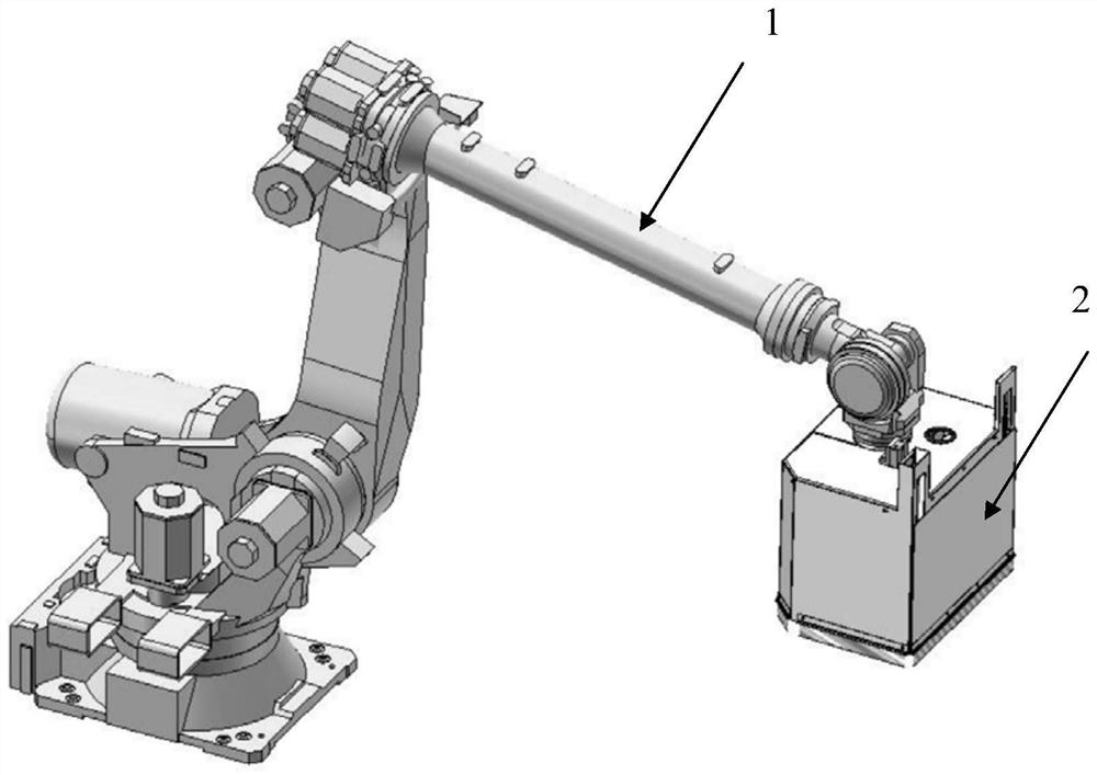
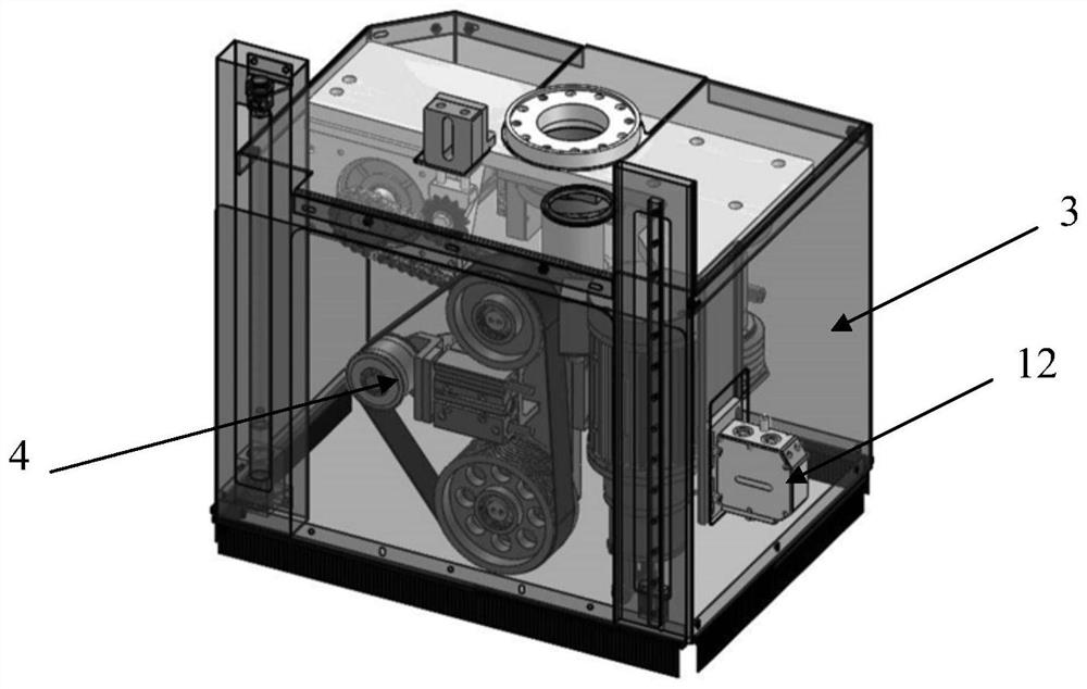
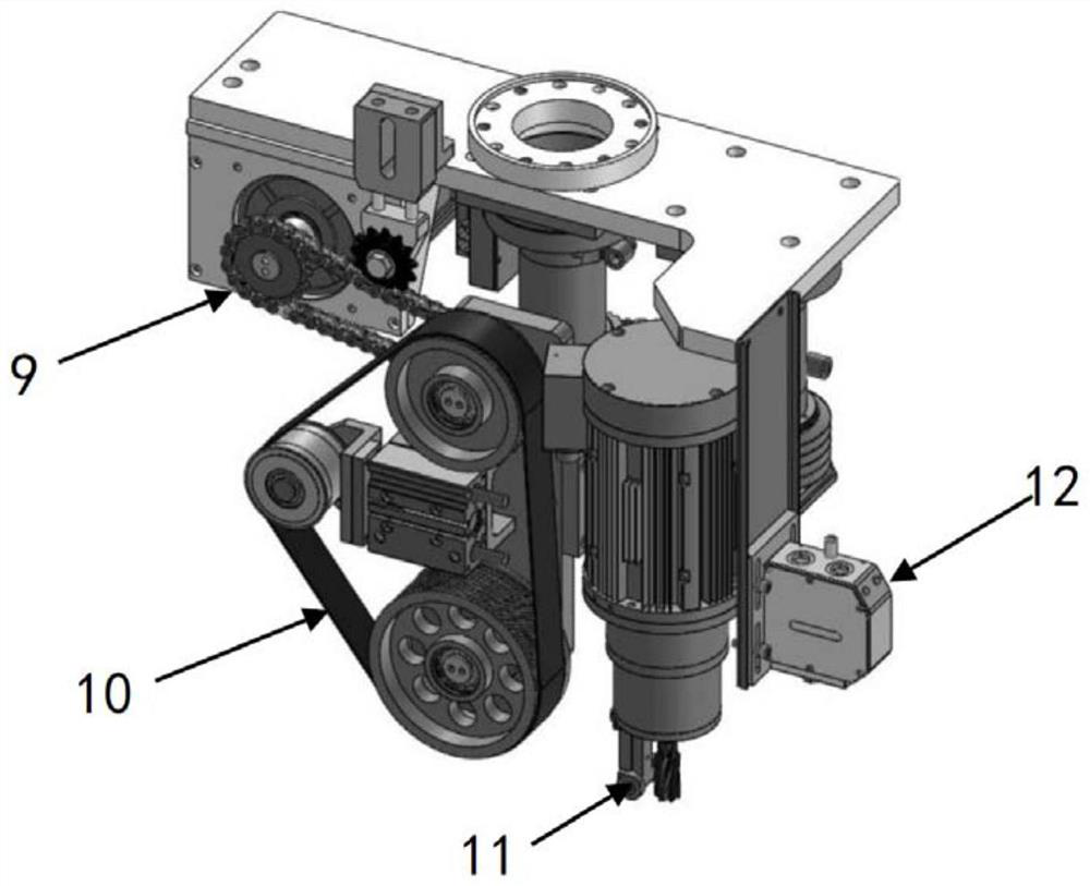
The invention provides detecting, milling and polishing equipment for workpiece welding seams, and belongs to the field of milling of large-allowance welding seams. The detecting, milling and polishing equipment comprises a manipulator, a polishing part, a workpiece detection assembly, a milling assembly, an abrasive belt polishing assembly and a chain rotating assembly, wherein the polishing part is connected to the head end of a manipulator body and used for polishing the surfaces of workpieces under the driving of the manipulator body so as to control the removal depth of welding seams, and the polishing part comprises a polishing mechanism and a protection mechanism; the polishing mechanism comprises a rack; the workpiece detection assembly is used for detecting the surfaces of the workpieces; the milling assembly is used for milling the surfaces of the workpieces according to detection results of the workpiece detection assembly; the abrasive belt polishing assembly is used for polishing the surfaces of the workpieces according to the detection results of the workpiece detection assembly; and the chain rotating assembly is used for driving the abrasive belt polishing assembly in real time according to the detection results of the workpiece detection assembly. By means of the treatment scheme, fine milling and polishing are conducted on the large-allowance welding seams in a targeted mode.

Description

technical field [0001] The invention relates to the field of milling of large margin welds, in particular to a workpiece weld inspection, milling and grinding equipment. Background technique [0002] In large-scale manufacturing industries such as high-speed rail, heavy industry and shipbuilding, there are a large number of large-scale component welding. Although the welding of large components has been gradually automated, due to the processing tolerances of large components, clamping positioning errors, welding thermal deformation and unstable welding processes, etc., there are large gaps in the weld position and margin after welding of large components. deviation. At present, for this type of weld, ordinary special-purpose equipment is not competent, and the relevant welds are mainly polished manually. [0003] However, manual grinding has disadvantages such as large grinding workload, harsh environment, low efficiency, difficult to guarantee product quality, and poor p...

Claims


Application Information

Patent Timeline
IPC IPC(8): B24B9/04B24B55/06B24B49/12B24B49/16B24B21/00B24B27/00B24B21/20B25J11/00B23C3/00B23C9/00
CPCB24B9/04B24B55/06B24B49/12B24B49/165B24B21/002B24B21/008B24B27/0076B24B21/20B25J11/0055B23C3/00B23C9/005
Inventor 胡小龙蔡路
Owner ANWHA SHANGHAI AUTOMATION ENG
Learn More