
Method for laser processing of CFRP material

A laser processing and laser technology, which is applied in laser welding equipment, metal processing equipment, metal material coating technology, etc., can solve the problems of difficult to achieve complex structure surface cladding, low coating deposition rate, low coating adhesion, etc. , to achieve the effects of high coating forming efficiency, uniform and dense coating, and good chip removal conditions

Pending Publication Date: 2021-12-31
JIANGSU UNIV
View PDF10 Cites 2 Cited by
  • Summary
  • Abstract
  • Description
  • Claims
  • Application Information

AI Technical Summary

Problems solved by technology

[0005] 1. The deposition rate of the existing coating is low, the cost is high, and it is difficult to achieve cladding on the surface of complex structures;
[0006] 2. The adhesion of the coating is low. Except for plasma spraying, the metal coating is only cured and bonded on the surface of the CFRP material, mainly mechanically bonded, and no chemical reaction occurs to realize the bond between atoms.

Method used


Image

  • Method for laser processing of CFRP material
  • Method for laser processing of CFRP material
  • Method for laser processing of CFRP material

Examples


Embodiment 1

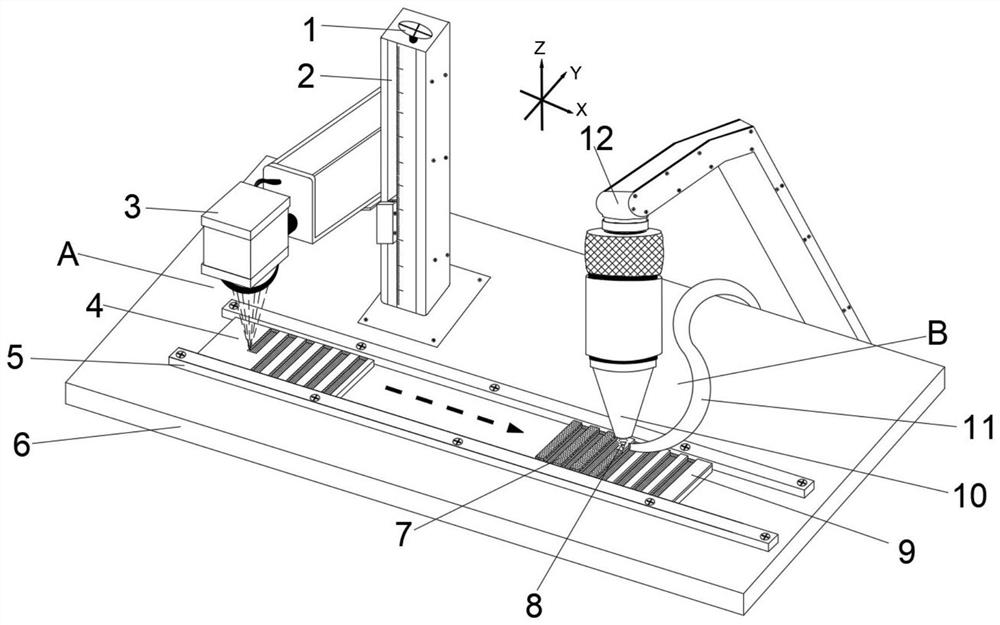
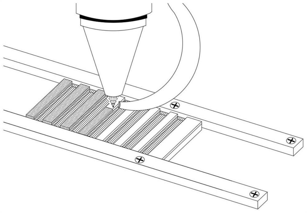
[0035] Example 1 as figure 1 , figure 2 and Figure 4 Shown, the method for laser processing CFRP material of the present invention, concrete steps are as follows:

[0036] A. Cut the polyphenylene sulfide (PPS)-based carbon fiber plate with a thickness of 3mm, a fiber content of 50%, and a unidirectional arrangement of fibers into squares of 3mm×30mm×50mm by wire cutting.

[0037] B. Pretreat the surface of CFRP plate 4 with laser degumming method. The pulse width of laser degumming is 200ns, the repetition frequency is 80KHz, the power is 100w, and the scanning speed is 2500mm / s, so that the surface carbon fiber is exposed, and the metal coating and wettability of carbon fiber;

[0038] C. Place the CFRP plate 4 that has been degummed on the fixed desktop 5, and fix it with the working table 6, and place it under the laser for laser milling and etching. Among them, the lifting axis 1 of the laser can adjust the vertical movement distance of the laser head, and the verti...

Embodiment 2

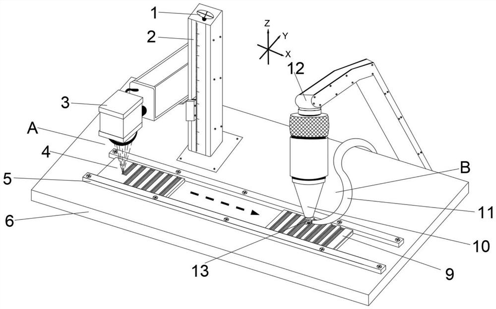
[0040] Example 2 as image 3 , Figure 4 and Figure 5 Shown, the method for laser processing CFRP material of the present invention, concrete steps are as follows:

[0041] A. Use wire cutting to cut the carbon fiber plate with epoxy resin as the matrix with a thickness of 4mm, a fiber content of 50%, and a unidirectional arrangement of fibers into squares of 4mm×30mm×50mm;

[0042] B. Pretreat the surface of the carbon fiber composite material plate by laser degumming method. The pulse width of laser degumming is 200ns, the repetition frequency is 80KHz, the power is 100w, and the scanning speed is 2500mm / s, so that the surface carbon fiber is exposed and the metal coating is increased at the same time wettability with carbon fiber;

[0043] C. Place the carbon fiber plate 4 that has been degummed on the fixed desktop 5, and fix it with the working table 6, and place it under the laser for laser milling and etching. Among them, the lifting axis 1 of the laser can adjust ...


PUM

PropertyMeasurementUnit
thicknessaaaaaaaaaa

Abstract

The invention provides a method for laser processing of a CFRP material. The method comprises the following steps: pretreating the plate surface of the CFRP material by using a laser degumming method, so that carbon fibers on the surface layer are exposed, and the wettability of a metal coating and the carbon fibers is improved; removing a material in a processing area on the surface of the CFRP plate layer by layer through laser, and forming micropores or microgrooves to realize patterning treatment on the surface of the CFRP plate; and conducting plating on the gaps between the adjacent micropores or microgrooves in the surface processing area of the CFRP plate through laser cladding. The method is easy to operate, low in cost and small in pollution, the milled groove is high in processing precision and small in heat affected zone, the prepared coating and the carbon fibers form metallurgical bonding, and a coating film is uniform and compact.

Description

technical field [0001] The invention relates to the field of laser processing of carbon fiber reinforced thermoplastic composite materials, in particular to a method for laser processing CFRP materials. Background technique [0002] Carbon fiber reinforced thermoplastic composites (CFRP) have unique advantages such as high specific strength and specific stiffness, strong designability, good fatigue fracture resistance, corrosion resistance and special electromagnetic properties, and have strong competition in many application fields. force. In practical applications, CFRP materials are used to partially replace metal materials in the reinforcement of most aerospace equipment and various bridge buildings. Taking the aircraft manufacturing industry as an example, airlines have successfully applied it to aircraft vertical tails, horizontal tails, fairings, cabin floor beams, elevators and other components, and the use of CFRP has gradually changed from only being applied to se...

Claims


Application Information

Patent Timeline
Patent Type & Authority Applications(China)
IPC IPC(8): B23K26/362B23K26/60C23C24/10
CPCB23K26/362B23K26/60C23C24/103
Inventor 叶云霞张子靖朱嘉鑫任旭东花银群
Owner JIANGSU UNIV
Learn More