
Venue shaped antenna

A shaping and antenna technology, applied in antennas, antenna coupling, antenna components, etc., can solve problems such as the difficulty of accurately determining the position of each antenna, the difficulty of accurately realizing the amplitude and phase of the excitation, and the complexity of the feeding network. Achieve the effects of reducing backward radiation, widening the half-power beam width, and improving isolation

Pending Publication Date: 2021-12-28
GUANGDONG ZHONGYUAN CREATIVE TECH CO LTD
View PDF0 Cites 0 Cited by
  • Summary
  • Abstract
  • Description
  • Claims
  • Application Information

AI Technical Summary

Problems solved by technology

These two methods can achieve better shaping characteristics, but the first method requires many antenna elements, which increases the preparation cost, and its feeding network is very complicated, so it is difficult to accurately realize the amplitude and phase of the excitation; the second method The disadvantage of the method is that it is achieved by controlling the position of the antenna, it is difficult to accurately determine the position of each antenna, which may lead to large side lobes

Method used


Image

  • Venue shaped antenna
  • Venue shaped antenna
  • Venue shaped antenna

Examples


Embodiment Construction

[0029] In order to facilitate the understanding of the present invention, the present invention will be described more fully below with reference to the accompanying drawings. Preferred embodiments of the invention are shown in the accompanying drawings. However, the present invention can be embodied in many different forms and is not limited to the embodiments described herein. The purpose of providing these embodiments is to make the disclosure of the present invention more thorough and comprehensive. It should be noted that the "first" and "second" mentioned in the present invention do not represent a specific number and order, but are only used to distinguish names.

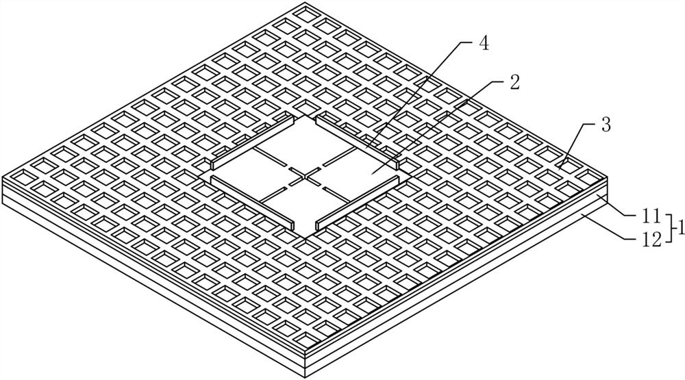
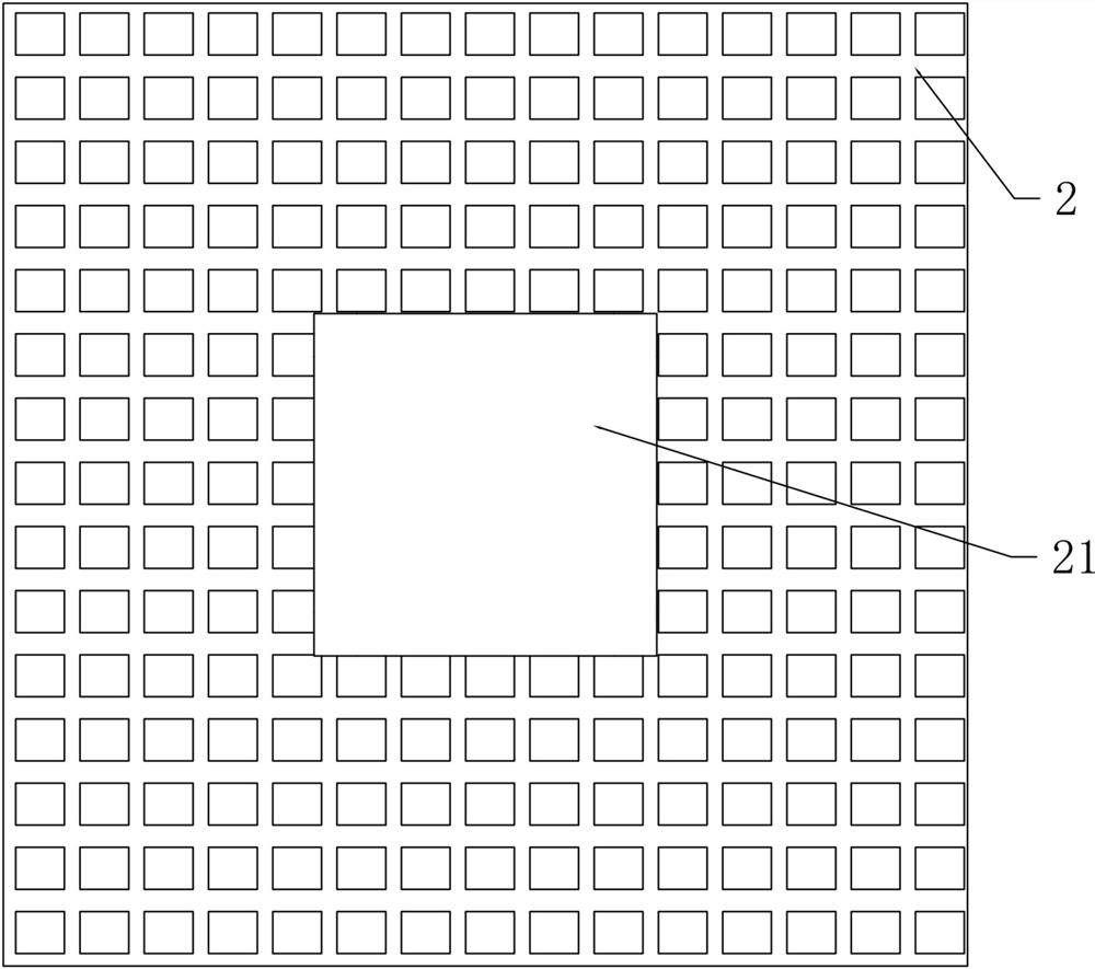
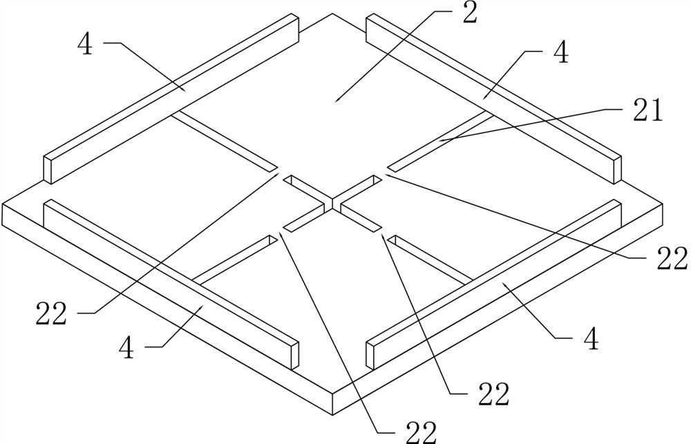
[0030] See attached Figure 1-6 As shown, in this embodiment, a venue-shaped antenna includes a dielectric substrate 1, a radiator 2, and a metasurface layer 3, wherein the dielectric substrate 1 includes a first substrate layer 11 and a second substrate layer that are stacked up and down. 12 , the metasur...


PUM


Abstract

The invention provides a venue shaped antenna. According to the scheme, the venue shaped antenna comprises a dielectric substrate, a radiator and a metasurface layer stacked on the upper surface of the dielectric substrate, and a mounting groove used for containing the radiator is formed in the middle of the metasurface layer; the radiator is provided with separation gaps along the center line in the length direction and the center line in the width direction, so that the radiator is divided into four radiation units which are arranged in a matrix, a connecting bridge is formed between any two adjacent radiation units, and the four radiation units are correspondingly connected through the four connecting bridges; therefore, the dual-polarization function is realized, the frequency band utilization rate, the front-to-back ratio of the antenna, the antenna gain, the half-power beam width of the antenna and the slope of -20dB beam width are improved, the side lobe of the antenna is reduced, and the antenna requirement of a venue is met.

Description

technical field [0001] The present invention relates to the technical field of wireless communication systems, in particular to a venue-shaped antenna. Background technique [0002] At present, 5G technology has been applied in various scenarios. For application scenarios such as competitions or live broadcast venues, the antenna radiation mechanism has an important impact on the transmission of game results or live broadcast signals. Among them, in a venue, it is often divided into Many sectors, in order to obtain the same signal in each position of the sector and avoid the situation of "darkness under the lights", the radiation direction of the antenna needs to have a good boundary, that is, to meet the half power beam width of the antenna (- 3 dB beamwidth) and -20dB beamwidth ratio is greater than a certain fixed value. At the same time, the antennas in the venue still need to meet the low side lobe function, otherwise it will affect the radiation of signals in other se...

Claims


Application Information

Patent Timeline
Patent Type & Authority Applications(China)
IPC IPC(8): H01Q1/36H01Q1/48H01Q1/50H01Q1/52H01Q15/00
CPCH01Q1/36H01Q1/50H01Q1/521H01Q1/48H01Q15/0086
Inventor 张伟强
Owner GUANGDONG ZHONGYUAN CREATIVE TECH CO LTD
Learn More