
Mode converter from rectangular waveguide TE10 mode to circular waveguide rotating TE11 mode

A technology of mode converter and rectangular waveguide, which is applied in the field of millimeter wave and terahertz devices, can solve the problems that the circular polarization mode cannot be directly obtained, large processing and assembly errors, large structural size, etc., and achieves low processing and assembly difficulty and easy processing High production and conversion efficiency

Active Publication Date: 2021-12-24
UNIV OF ELECTRONICS SCI & TECH OF CHINA
View PDF2 Cites 1 Cited by
  • Summary
  • Abstract
  • Description
  • Claims
  • Application Information

AI Technical Summary

Problems solved by technology

However, the circular polarization mode cannot be obtained directly, and a mode converter needs to be used
The existing circular polarization TE11 mode converters are mostly used in the microwave and millimeter wave low-end frequency bands, with large structural dimensions and relatively simple processing, but there are serious processing problems in the millimeter wave high-end and terahertz low-end frequency bands, which cannot be directly applied.
The existing circular polarization mode converters for high-frequency bands have complex structures, large processing and assembly errors, and serious energy leakage. Therefore, it is necessary to design a new type of circular polarization mode converters that can be applied to the technical field of millimeter wave and terahertz devices.

Method used


Image

  • Mode converter from rectangular waveguide TE10 mode to circular waveguide rotating TE11 mode
  • Mode converter from rectangular waveguide TE10 mode to circular waveguide rotating TE11 mode
  • Mode converter from rectangular waveguide TE10 mode to circular waveguide rotating TE11 mode

Examples


Embodiment 1

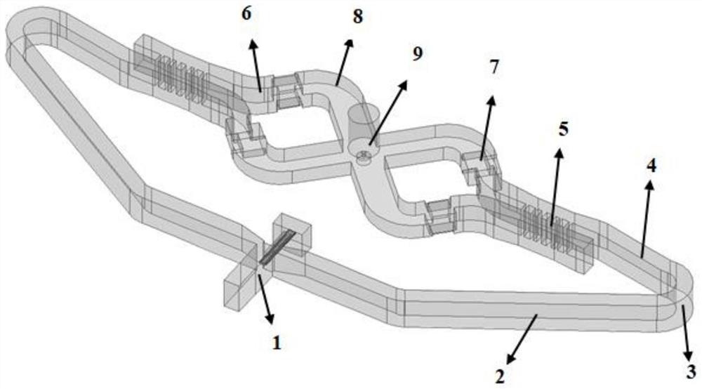
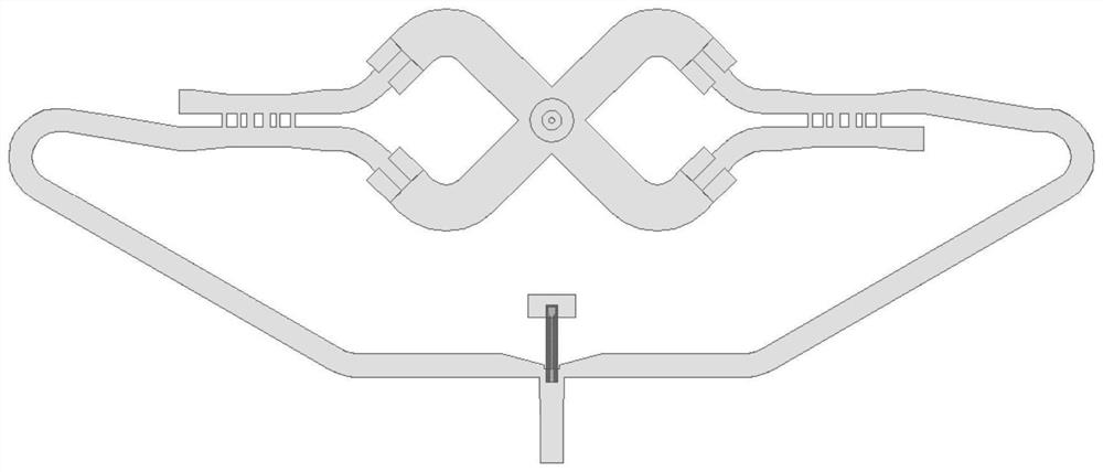
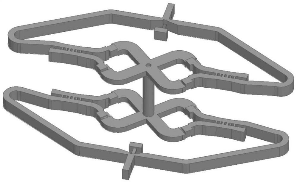
[0026] This embodiment provides a mode converter from a rectangular waveguide TE10 mode to a circular waveguide rotating TE11 mode with a center frequency of 220 GHz, the structure is as follows figure 1 and figure 2 As shown, it includes a coplanar magic T structure 1, two bent waveguides, two 3dB couplers 5, four 45° arc bent waveguides 6, four 90° waveguide twisters 7, and four 90° arcs curved waveguide 8 and a 4-way combiner 9 .

[0027] The coplanar magic T structure 1 includes a rectangular waveguide input port, a first rectangular waveguide output port, a second rectangular waveguide output port and an isolation port using a microstrip probe output, the first rectangular waveguide output port and the second rectangular waveguide output port The ports are respectively connected to the input end of the corresponding 3dB coupler 5 by bending 180° through the corresponding bent waveguide, and the bent waveguide is composed of a long inclined waveguide 2, a 150° circular a...


PUM


Abstract

The invention discloses a mode converter from a rectangular waveguide TE10 mode to a circular waveguide rotating TE11 mode. The mode converter comprises a coplanar magic T structure, a four-path synthesizer, a plurality of bent waveguides, two 3dB couplers and four 90-degree waveguide twisters. Two output ports of the coplanar magic T structure are respectively bent by 180 degrees through the corresponding bent waveguides and are connected to the input ends of the corresponding 3dB couplers; the two 3dB couplers are in central symmetry about the central axis of the four-path synthesizer, and the straight-through ends and the coupling ends of the 3dB couplers are connected to the input ends of the four-path synthesizer through the corresponding 90-degree waveguide twisters respectively. The two 90-degree waveguide twisters connected with the same 3dB coupler are in 180-degree rotational symmetry about the central axis of the 3dB coupler along the electromagnetic signal transmission direction; and the two pairs of 90-degree waveguide twisters connected with the different 3dB couplers are in plane symmetry about the symmetry plane of the four-path synthesizer. The mode converter has the advantages of simplicity and convenience in design, high mode purity, easiness in processing and manufacturing and high conversion efficiency.

Description

technical field [0001] The invention belongs to the technical field of millimeter waves and terahertz devices, and in particular relates to a mode converter from a rectangular waveguide TE10 mode to a circular waveguide rotating TE11 mode. Background technique [0002] In a modern communication transmission system, the power amplifier determines the transmission output power of the system, which in turn affects the system's working distance, work efficiency and other indicators. Although traditional vacuum electronic devices can output up to hundreds of watts of power, their unfavorable factors of large volume, small bandwidth, and high processing difficulty have led to them being gradually replaced by solid-state semiconductor devices. In contrast, solid-state semiconductor devices are small in size and long-lasting Long, low working voltage and can be processed and produced in batches, which have more advantages. However, as the operating frequency increases, the output p...

Claims


Application Information

Patent Timeline
IPC IPC(8): H01P1/16
CPCH01P1/16
Inventor 张勇张博代春玥张铁笛胡江
Owner UNIV OF ELECTRONICS SCI & TECH OF CHINA
Learn More