


Quick Research
Generate reliable direction feasibility study reports for your R&D in just a few steps.

Technical Q&A
Discover and master advanced knowledge NOW. Basics, ideas, possibilities, all at once.

Find Solutions
As an expert in R&D theories, this can generate solutions to your technical problems instantly.

Evaluate Feasibility
Analyze your overall solution with one click, know your potential R&D risks in advance.

Monitor Landscape
Get weekly tech updates, stay abreast of the latest tech innovations and key insights.
Distributed CP unified deployment method, network equipment and storage medium
A distributed and unified technology, applied in data exchange networks, wide area networks, transmission systems, etc., can solve the problems of inability to realize rapid deployment, inability to realize distributed deployment of stacked network elements, and inability to realize vBRAS-CP distributed architecture. The effect of reducing human workload, fast deployment speed, and convenient deployment
- Summary
- Abstract
- Description
- Claims
- Application Information
AI Technical Summary
Problems solved by technology
Method used
Image

Examples
example 1
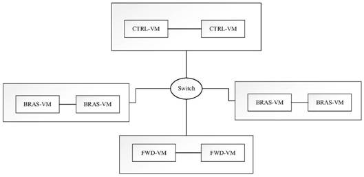
[0055] Example 1: CTRL-VM number 2;
[0056] The number of BRAS-VMs is 4;
[0057] FWD-VM number 2;
[0058] CTRL-VM network element label number range: 1-2;
[0059] BRAS-VM network element number range: 97-100;
[0060] FWD-VM NE tag number range: 5-6.
[0061] The internal channel Vlan and network segment realize the internal communication between different types of network elements.
[0062] The uploaded files are not limited to basic configuration template files, but also image file compression packages containing different types of NE image files. The image file determines the operating system of the NE to be deployed, so different types of NE require different image files. The image file is used during network element configuration, so the image file does not have to be uploaded at this step, as long as it is done before starting the network element configuration.
[0063] 0005: The VNF management server parses the basic configuration template file, and confirms t...
Embodiment 2
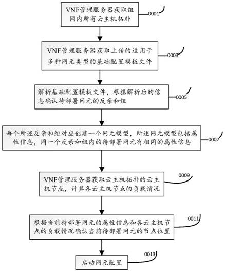
[0100] The distributed CP unified deployment method is applied to the VNF management server to obtain the topology of all cloud hosts in the network; obtain and upload basic configuration template files applicable to various network element types; After the anti-affinity group of the element is created, a network element model is created for each anti-affinity group. The network element model includes attribute information, and the network elements to be deployed in the same anti-affinity group have the same attribute information; obtain the cloud host The computing nodes of the topology calculate the load of each cloud host node; confirm the node position of the current to-be-deployed network element according to the attribute information of the current to-be-deployed network element and the load of each cloud host node; start the network element configuration, such as Figure 4 shown.
[0101] As a preference of this embodiment, parsing the basic configuration template file,...
PUM
 Abstract
Description
Claims
Application Information
 - R&D Engineer
- R&D Manager
- IP Professional
- Industry Leading Data Capabilities
- Powerful AI technology
- Patent DNA Extraction
Browse by: Latest US Patents, China's latest patents, Technical Efficacy Thesaurus, Application Domain, Technology Topic, Popular Technical Reports.
© 2024 PatSnap. All rights reserved.Legal|Privacy policy|Modern Slavery Act Transparency Statement|Sitemap|About US| Contact US: help@patsnap.com