Steel pile casing positioning device and method for steel sheet pile hole guiding construction

A technology of positioning device and steel casing, which is applied in the direction of sheet pile walls, foundation structure engineering, construction, etc., can solve the problems of poor positioning ability of steel casing, difficulty in inserting and driving steel sheet piles, and not being on the same plane, and achieve the goal of supporting equipment Less, meet the needs of special geological conditions, and easy to accept the effect

Active Publication Date: 2021-12-07
南昌交通学院
View PDF7 Cites 0 Cited by
  • Summary
  • Abstract
  • Description
  • Claims
  • Application Information

AI Technical Summary

Problems solved by technology

[0007] ②When the driving force of the steel sheet pile exceeds a certain value, it may be slow to drive or cannot be driven;
[0009] ④ However, since the ground where the project is located is often not on the same plane, there is usually no construction guide frame on site, but steel casings are used for positioning
In weak strata, the positioning ability of the steel casing is poor, and it tends to displace along with the vibration of the drilling machinery during the construction of the drilling, and this displacement is difficult to be found and even more difficult to control, resulting in The deviation of the lead hole brings difficulties to the insertion and driving of the steel sheet pile. The failed lead holes are as follows: figure 2 shown

Method used


Image

  • Steel pile casing positioning device and method for steel sheet pile hole guiding construction
  • Steel pile casing positioning device and method for steel sheet pile hole guiding construction
  • Steel pile casing positioning device and method for steel sheet pile hole guiding construction

Examples


Embodiment Construction

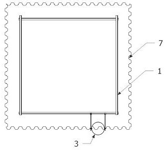
[0039] like image 3 and Figure 4 As shown, this embodiment is a steel casing positioning device for steel sheet pile lead hole construction, including positioning guide frame 1, steel pipe positioning pile 2, steel casing 3, anchor pin device 4, positioning buckle 5 and steel sheet pile insertion slot Frame 6.

[0040] like Figure 5 As shown, the positioning guide frame 1 is fixed on the positioning pile 2 by welding the fixed steel plate.

[0041] like Image 6 As shown, the steel casing 3 of this embodiment is connected to the positioning buckle 5 through the fixing rod 41 of the anchor pin device 4 . The positioning buckle 5 is installed on the positioning guide frame 1, that is, it is fixed on the I-beam 11 of the positioning guide frame, and the positioning buckle 5 is realized by the tightness of the top elastic knob handle 51 and the side elastic knob handle 55. The stepless adjustment of the horizontal position on the beam 11; the outer side of the positioning ...


PUM


Abstract

The invention provides a steel pile casing positioning device and method for steel sheet pile hole guiding construction. The device comprises a positioning guide frame (1), a steel pipe positioning pile (2), a steel pile casing (3), an anchoring pin device (4), a positioning buckle (5) and a steel sheet pile inserting and punching clamping groove frame (6). The positioning guide frame is fixed to the positioning pile, and the positioning buckle is arranged on I-shaped steel of the positioning guide frame and connected with the steel pile casing through the anchoring pin device; the anchoring pin device is formed by connecting a fixing rod (41) capable of freely rotating and a fixing anchor block (42); and the steel pile casing is connected to the positioning buckle through the fixing rod of the anchoring pin device, and stepless adjustment of the transverse position of the positioning buckle on the I-shaped steel is achieved through loosening and tightening of a top and lateral loosening and tightening rotary knob handle. According to the steel pile casing positioning device and method for steel sheet pile hole guiding construction, the problem that for a long time, in the steel sheet pile inserting and punching construction process, correct positioning and perpendicularity control cannot be achieved is solved, the quality and efficiency of steel sheet pile cofferdam construction are greatly improved, construction operation is convenient, the number of matched devices is small, and the construction cost can be greatly reduced.

Description

technical field [0001] The invention relates to a steel casing positioning device and method for steel sheet pile lead hole construction, belonging to the technical field of civil engineering. Background technique [0002] The steel sheet pile is a kind of steel structure with linkages on the edge, and the linkages can be freely combined to form a continuous and compact retaining wall or retaining wall. [0003] With the development of my country's traffic engineering construction, the design of bridges must not only meet the traffic requirements across rivers, lakes and seas. But also need to meet the environment, landscape and geographical location requirements. In design, in order to ensure the safety of navigation and the maximum flow during flood discharge, the pier foundation in water is designed as a low pile cap, so that the cap is completely buried under the river bed, and the foundation groove of the cap cannot be formed by sucking mud. Vertical excavation is req...

Claims


Application Information

Patent Timeline
Patent Type & Authority Applications(China)
IPC IPC(8): E02D19/04E02D13/04E02D5/68E02D5/04
CPCE02D19/04E02D13/04E02D5/68E02D5/04Y02E10/50
Inventor 李明华王万里洪莹彭茂龙
Owner 南昌交通学院
Why Eureka
Try Eureka