
Device and method for removing particulate matters in flue gas

A particulate matter and flue gas technology, applied in chemical instruments and methods, separation methods, combined devices, etc., can solve the problems of not eliminating pollutants, difficult to effectively remove condensable particulate matter, and small physical size, and the number of days to reach haze weather. The effect of reducing, reducing PM2.5 content, and removing the effect is obvious

Active Publication Date: 2021-12-07
CHINA PETROLEUM & CHEM CORP +1
View PDF3 Cites 0 Cited by
  • Summary
  • Abstract
  • Description
  • Claims
  • Application Information

AI Technical Summary

Problems solved by technology

Because the physical size of such substances is too small (micron scale), the existing process technology can effectively remove filterable particulate matter, but it is difficult to effectively remove condensable particulate matter
Or through the mixing of flue gas and flue gas or hot air to achieve the purpose of eliminating white smoke, but this technology does not eliminate pollutants, but only dilutes them

Method used


Image

  • Device and method for removing particulate matters in flue gas
  • Device and method for removing particulate matters in flue gas

Examples


Embodiment example 1

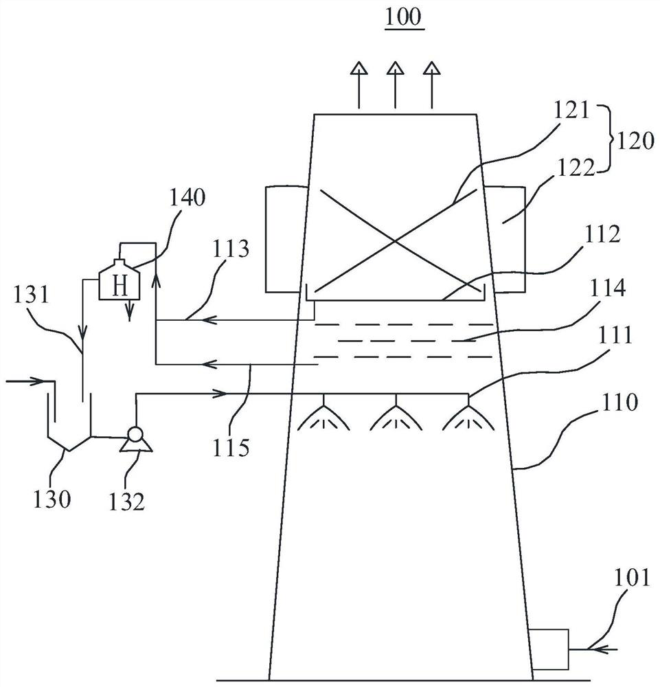
[0059] Such as figure 1 The device shown, process conditions: containing 1.7wt% magnetic seed spray liquid, the droplet particle size produced by the nozzle is not more than 20 μm, the field strength of the high-gradient magnetic separator 120 is 1.9T, and after running for 1.5 hours, the magnetic The medium is washed once, and the magnetic medium is bristle medium, and its material is mainly iron-cobalt alloy. The data before and after the treatment of particulate matter in flue gas are shown in Table 1.

[0060] Table 1 Situation before and after flue gas treatment

[0061] Test items Abbreviation before processing after treatment Removal rate filterable particles FPM 11.50mg / Nm 3

Embodiment example 2

[0063] Such as figure 1 The device shown, process conditions: containing 1.9% magnetic seed spray liquid, the droplet size produced by the nozzle is not greater than 20μm, the field strength of the high-gradient magnetic separator 120 is 2.2T, and the operation time is 1.5 hours. Rinse once, the magnetic medium is rigid mesh, and its material is mainly iron-cobalt alloy. The data before and after the treatment of particulate matter in flue gas are shown in Table 2.

[0064] Table 2 Situation before and after flue gas treatment

[0065] Test items Abbreviation before processing after treatment Removal rate filterable particles FPM 22.67mg / Nm 3

Embodiment example 3

[0067] Such as figure 1 The device shown, process conditions: containing 2.3% magnetic seed spray liquid, the droplet size produced by the nozzle is not greater than 20μm, the field strength of the high gradient magnetic separator 120 is 3.1T, and after 1.2 hours of operation time, the magnetic medium Rinse once, the magnetic medium is bristles, and its material is mainly iron-cobalt alloy. The data before and after the treatment of particulate matter in flue gas are shown in Table 3 below.

[0068] Table 3 Situation before and after flue gas treatment

[0069] Test items Abbreviation before processing after treatment Removal rate filterable particles FPM 18.75mg / Nm 3

3.66mg / Nm 3

80.48% Condensable particulate matter CPM 56.82mg / Nm 3

4.68mg / Nm 3

91.76%

[0070] It can be seen from the processing results of the above three implementation cases that the device 100 and method for removing particulate matter in flue g...


PUM

PropertyMeasurementUnit
particle diameteraaaaaaaaaa
sizeaaaaaaaaaa

Abstract

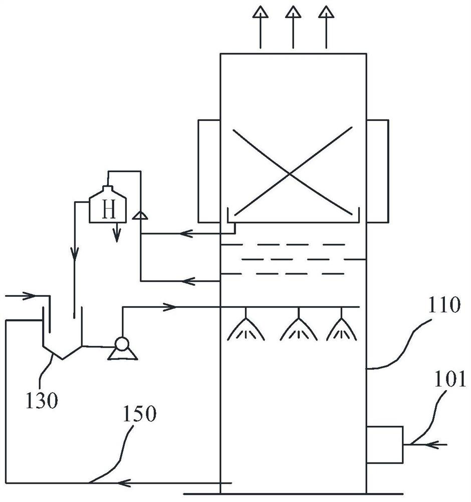
The embodiment of the invention relates to the technical field of flue gas treatment and provides a device and method for removing particulate matter in flue gas. The device comprises a reactor and a high-gradient magnetic separator, a magnetic seed spraying mechanism and a collecting disc are arranged in the reactor from bottom to top, a flue gas inlet is formed in the position, below the magnetic seed spraying mechanism, of the bottom of the reactor, and a first collecting pipe is communicated with the bottom of the collecting disc and extends out of the reactor; and the high-gradient magnetic separator comprises a magnetic conductive medium unit and a high-gradient magnetic field generator, the magnetic conductive medium unit is arranged in the reactor and located above the collecting disc, and the high-gradient magnetic field generator is arranged at the position, corresponding to the magnetic conductive medium unit, outside the reactor. The method comprises the step of removing the particulate matters in the flue gas by adopting the device. The device and the method have a very good removal effect on the particulate matters in the flue gas.

Description

technical field [0001] The invention relates to the technical field of flue gas treatment, in particular to a device and method for removing particulate matter in flue gas. Background technique [0002] The particulate matter emitted by stationary pollution sources is one of the important sources of particulate matter in the atmosphere, which has an important impact on the formation of regional haze weather. [0003] The particulate matter emitted by stationary pollution sources is divided into filterable particulate matter and condensable particulate matter. The U.S. EPA defines condensable particulate matter as follows: primary emission particulate matter belonging to a fixed emission source, which exists in gaseous form in the flue gas in the flue state, and is immediately condensed or reacted into a solid or liquid state after being discharged into the atmosphere through the chimney Particulate matter, condensable particulate matter condensation nuclei are usually below...

Claims


Application Information

Patent Timeline
Patent Type & Authority Applications(China)
IPC IPC(8): B01D50/00
CPCB01D50/00
Inventor 黄延召齐文义李小苗陈千惠孟学峰邓向军
Owner CHINA PETROLEUM & CHEM CORP
Learn More