
Combined cooling method and system for battery pack and charging pile of electric vehicle

A combined cooling technology for electric vehicles, applied to secondary batteries, secondary battery testing, heating/cooling equipment, etc., can solve the problems of lack of effective cooling at the charging interface, heat dissipation power can not meet the demand, etc., to achieve high latent heat, charging power The effect of improving and improving temperature uniformity

Active Publication Date: 2021-12-03
INST OF ELECTRICAL ENG CHINESE ACAD OF SCI
View PDF9 Cites 0 Cited by
  • Summary
  • Abstract
  • Description
  • Claims
  • Application Information

AI Technical Summary

Problems solved by technology

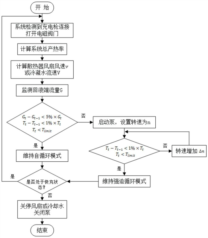
[0004] In order to solve the above problems in the prior art, that is, the heat dissipation power of the traditional battery pack and charging pile heat dissipation method in the fast charging scene cannot meet the demand, and the charging interface lacks effective cooling problem, the present invention provides a combined cooling method for electric vehicle battery packs and charging piles, the combined cooling method includes:

Method used


Image

  • Combined cooling method and system for battery pack and charging pile of electric vehicle
  • Combined cooling method and system for battery pack and charging pile of electric vehicle
  • Combined cooling method and system for battery pack and charging pile of electric vehicle

Examples


Embodiment Construction

[0060] The application will be further described in detail below in conjunction with the accompanying drawings and embodiments. It should be understood that the specific embodiments described here are only used to explain related inventions, not to limit the invention. It should also be noted that, for the convenience of description, only the parts related to the related invention are shown in the drawings.

[0061] It should be noted that, in the case of no conflict, the embodiments in the present application and the features in the embodiments can be combined with each other. The present application will be described in detail below with reference to the accompanying drawings and embodiments.

[0062] A combined cooling method for an electric vehicle battery pack and a charging pile according to the present invention, the combined cooling method includes:

[0063] Step S10, when it is detected that the electric vehicle is in the fast charging state, start the condenser fan...


PUM


Abstract

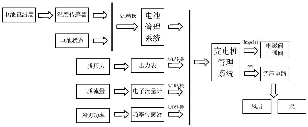
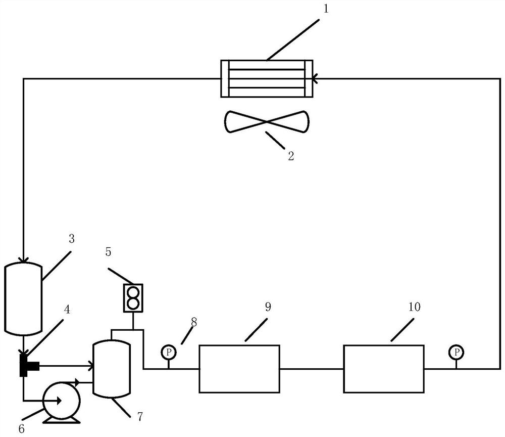
The invention belongs to the technical field of rapid charging and cooling of electric vehicles, particularly relates to a combined cooling method and system for a battery pack and a charging pile of an electric vehicle, and aims to solve the problems that in a rapid charging scene, the heat dissipation power of a traditional battery pack and charging pile heat dissipation mode cannot meet the requirement, and a charging interface lacks effective cooling. The method comprises the following steps of: starting self-circulation cooling in a rapid charging state; calculating total heat production, and acquiring a condenser air speed or condensate water flow speed at the current moment; if the system cooling is in a steady state within the time delta t, maintaining self-circulation, otherwise, starting a circulating pump and enabling the circulating pump to operate at a preset rotating speed n, and entering a forced circulation mode; if the system cooling is in a steady state within the time delta t, maintaining a rotating speed of the circulating pump, otherwise, adjusting the rotating speed increment of the circulating pump; and repeatedly executing the steps until the electric vehicle stops rapid charging, and turning off a condenser fan and the circulating pump. The charging pile and the battery pack are cooled at the same time, cost and system energy consumption are reduced, and charging safety and the cooling effect are improved.

Description

technical field [0001] The invention belongs to the technical field of rapid charging and cooling of electric vehicles, and in particular relates to a combined cooling method and system for electric vehicle battery packs and charging piles. Background technique [0002] Under the dual promotion of energy security and green transportation, electric vehicles have developed rapidly in recent years. Lithium-ion batteries have become the main power source of electric vehicles due to their high energy density, high power density, and long cycle life. However, due to the dependence of battery parameters on usage conditions, lithium-ion batteries still face some difficulties and challenges in practical applications. Compared with traditional fuel vehicles, the charging time of electric vehicles is greatly extended, and the battery pack even takes 8 to 10 hours to be fully charged under slow charging conditions. The key to solving charging time anxiety is the popularization and app...

Claims


Application Information

Patent Timeline
IPC IPC(8): H01M10/6569H01M10/651H01M10/625H01M10/613H01M10/48H01M10/46H01M10/42B60H1/32B60H1/00
CPCH01M10/613H01M10/625H01M10/651H01M10/6569H01M10/46H01M10/486H01M10/4285H01M10/425B60H1/00007B60H1/00457B60H1/00642B60H1/00814B60H1/32B60H2001/00114B60H2001/0015Y02E60/10Y02T10/70Y02T10/7072Y02T90/12
Inventor 阮琳王军
Owner INST OF ELECTRICAL ENG CHINESE ACAD OF SCI
Learn More