Lossless implementation method for laser-induced breakdown spectroscopy component detection and application thereof
A technology of laser-induced breakdown and composition detection, which is applied in thermal excitation analysis, material excitation analysis, and material analysis through optical means, and can solve problems such as ablation damage, weakening of spectral signal propagation, and reduction of test accuracy and reliability. , to achieve the effect of reducing ablation, avoiding excessive loss, and reducing loss
- Summary
- Abstract
- Description
- Claims
- Application Information
AI Technical Summary
Problems solved by technology
Method used
Image

Examples
experiment example 1
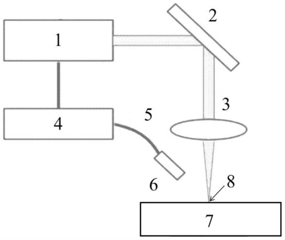
[0062] Such as figure 1 As shown, it is a schematic diagram of a laser-induced breakdown spectroscopy detection device in an atmospheric environment disclosed in this experimental example. In this method, 1 is a laser, 2 is a reflector, 3 is a focusing mirror, 4 is a spectrometer, and 5 is an optical fiber. , 6 is the receiving head, 7 is the material to be tested, and 8 is the focusing position of the laser beam. After the laser beam generated by the laser 1 is reflected by the mirror 2 and focused by the focusing mirror 3, it directly irradiates the surface of the material to be tested to form ablation And during the excitation effect of the material, the other end of the laser 1 is connected to a spectrometer 4, and the spectrometer 4 collects spectral signals through the optical fiber 5 and the receiving head 6, and then analyzes information such as element types and composition content on the surface of the material. In the process, the laser beam focusing position 8 is o...
experiment example 2
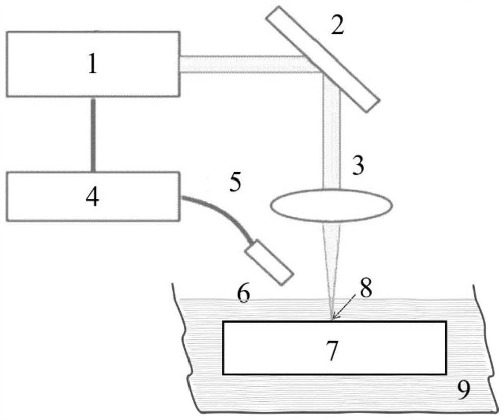
[0066] Such as figure 2 As shown, it is a schematic diagram of a laser-induced breakdown spectroscopy detection device in an atmospheric environment disclosed in this experimental example. The difference from Experimental Example 1 is that the material 7 to be detected is completely located in the underwater environment 9, and the rest of the settings are the same as in Experimental Example 1. .
[0067] In this method, the laser beam passes through the underwater environment 9 to irradiate the surface of the material 7 to be detected, and in the process of forming ablation and material excitation effects, the spectrometer 4 collects spectral signals through the receiving head 6, and then analyzes the element types on the surface of the material and content of ingredients. In this process, the laser beam focus position 8 is on the material surface, that is, the laser beam is in a state of no defocus relative to the material surface; in addition, the propagation of the laser ...
Embodiment 1
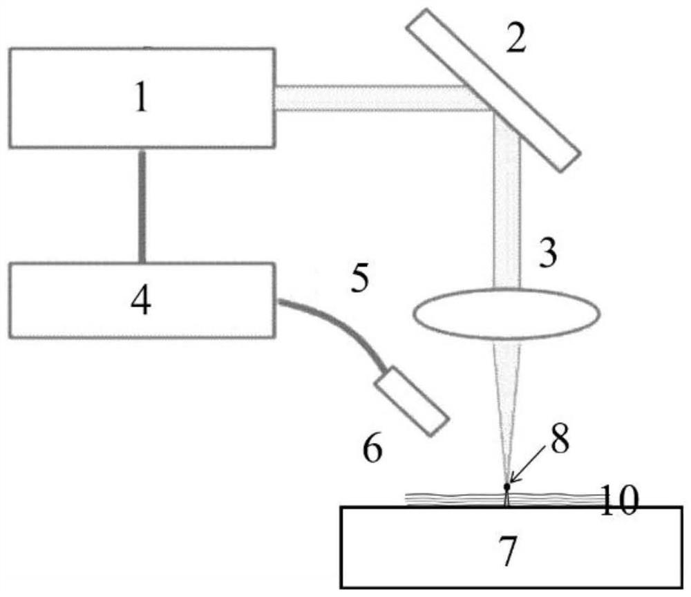
[0069] Such as image 3 As shown, it is a schematic diagram of a laser-induced breakdown spectrum detection device in an atmospheric environment disclosed in this embodiment. The laser beam generated by the laser 1 is reflected by the reflector 2 and focused by the focusing mirror 3, and then passes through the water confinement layer 10 to radiate During the process of irradiating the surface of the material to be tested by irradiating the surface of the material to be tested to form ablation and material excitation effects, the other end of the laser 1 is connected to a spectrometer 4, and the spectrometer 4 collects spectral signals through the optical fiber 5 and the receiving head 6, and then analyzes the material. Information such as the type and content of elements on the surface. In the process, the laser beam focusing position 8 is above the water confinement layer 10 on the material surface, that is, the laser beam is in a positive defocus state relative to the mater...
PUM
| Property | Measurement | Unit |
|---|---|---|
| Thickness | aaaaa | aaaaa |
| Thickness | aaaaa | aaaaa |
| Wavelength | aaaaa | aaaaa |
Abstract
Description
Claims
Application Information
 - R&D
- Intellectual Property
- Life Sciences
- Materials
- Tech Scout
- Unparalleled Data Quality
- Higher Quality Content
- 60% Fewer Hallucinations
Browse by: Latest US Patents, China's latest patents, Technical Efficacy Thesaurus, Application Domain, Technology Topic, Popular Technical Reports.
© 2025 PatSnap. All rights reserved.Legal|Privacy policy|Modern Slavery Act Transparency Statement|Sitemap|About US| Contact US: help@patsnap.com